2.0 06/2012 © CAME Cancelli Automatici S.p.A. - The data and information in this manual may be changed at any time and without obligation on the part of Came Cancelli Automatici S.p.A. to notify said changes.
ENGLISH
Description
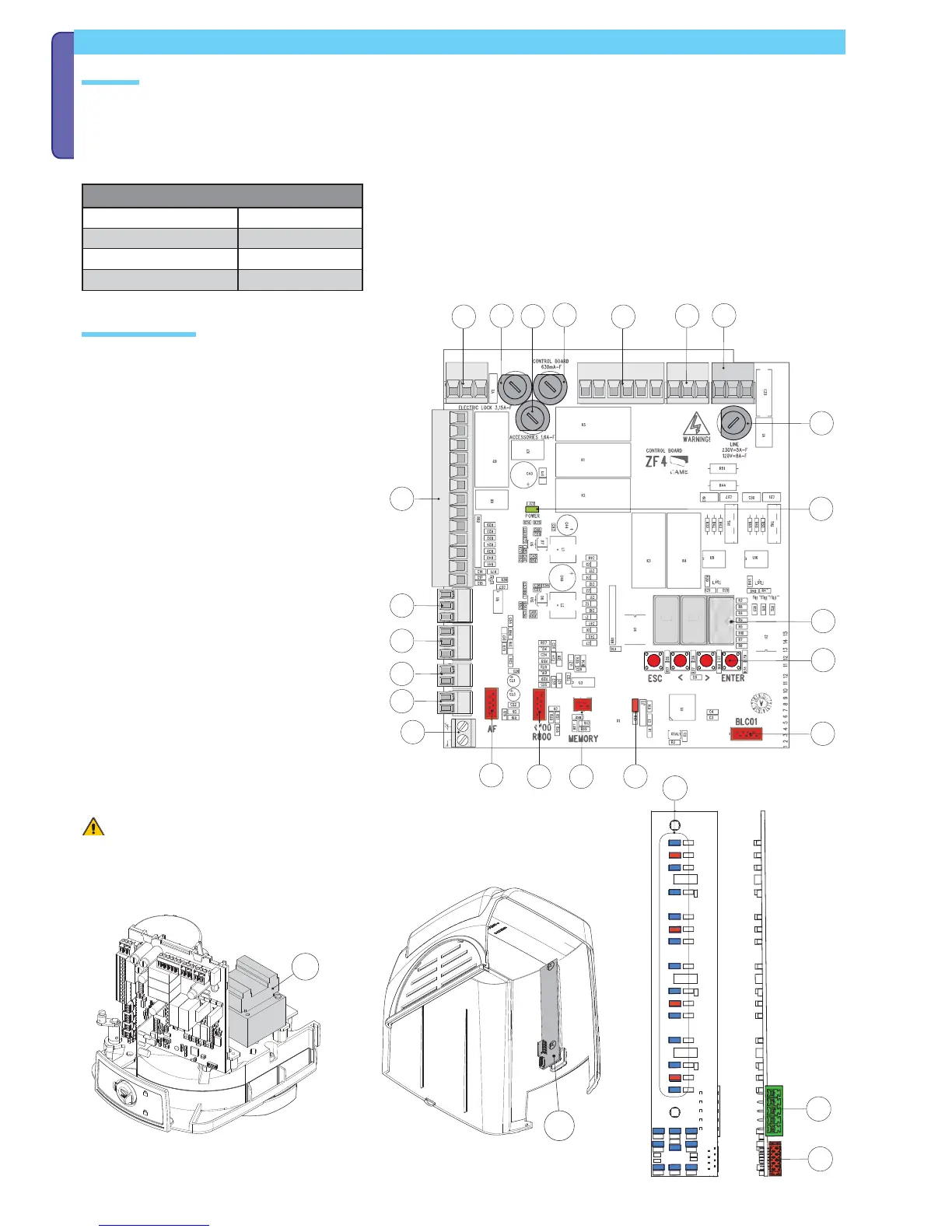
Main component parts
Command and control electronics
The control panel should be powered by 230 V AC, at 50/60 Hz frequency.
the command devices and accessories are powered by 24 V. The accessories must not exceed 50 W overall.
All connections are protected by quick fuses, see table.
The functions on the entry and exit contacts, the time settings and user management, are all set and viewable on the display which is managed by the
software.
Warning! Before acting on the control panel, cut off
the power supply.
1 Transformer
2 V power supply terminals
3 Transformer terminals
4 Gearmotor terminals
5 Command and safety device terminals
6) Encoder terminals
7 Terminals for transponder-based devices
8 Keypad selector terminals
9 Antenna terminals
10 Electro-lock fuse
11 -Accessories fuse
12 Board fuse
13 Line fuse
14 power on voltage present LED warning light
15 Programming indicator LED
16 Display
17 Programming buttons
18 FA001 board connector
19 Memory roll card connector
20 700 R800 or R800 card connector
21 AF card connector
22 FA001 board
23 4 Connector for connecting to the ZF4 card
24 001 Terminals for connecting the second FA001 card
25 25 LED to signal gate status
FUSE TABLE
Line fuse
5 A-F
Accessories fuse
1.6 A-F
Control unit fuse 630 mA-F
Electro-lock fuse 3.15 A-F