A
E
120 min.
C
47,5
310 max.
200 min.
173
81,5
40
120
100
60
18
p. 88 - Manual code: 119 DW 0 2119DW 0 2 ver. 2. 02. 0 06/2012 © CAME Cancelli Automatici S.p.A. - The data and information in this manual may be changed at any time and without obligation on the part of Came Cancelli Automatici S.p.A. to notify said changes.
ENGLISH
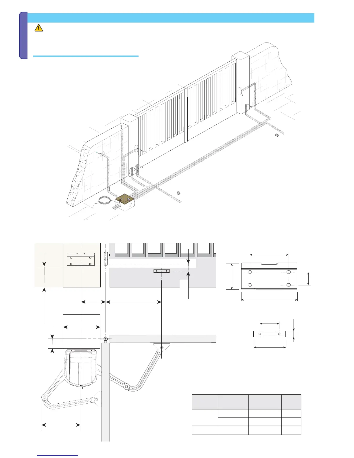
Installation
Opening
angle
ACE
90°
140 0÷200 420
160÷180 200 380
110° 200÷220 0÷50 400
Note: the drawings are for installing the left-side gearmotor. Installing the right-side gearmotor is symmetrical.
Determine the most suitable point to fasten the gate bracket while respecting the distances (mm) shown in the drawing on the table below.
The following illustrations are just examples, in that the space for securing the operator and accessories depends on the installation zone. It
is up to the installer to choose the most suited solution.
Set up the necessary corrugated tubing (Ø 25 mm) for connections coming
from the junction pit.
N.B.: the number of tubes depends on the type of accessories featured.
You need to set up two corrugate tubes where the FA40230CB operator will
be installed.
Laying the corrugated tubing and fastening the brackets