2.0 06/2012 © CAME Cancelli Automatici S.p.A. - The data and information in this manual may be changed at any time and without obligation on the part of Came Cancelli Automatici S.p.A. to notify said changes.
ENGLISH
Types and thickness of cables
N.B.: If cables are of a different length than that shown in the table, determine the cable section based on the actual draw and the number of connected
devices and according the what is set forth in the CEI EN 60204-1 code of regulations.
For connections featuring several loads on the same line (i.e. sequential ones), the dimensions shown on the table must be reconsidered according to
the total draw and actual distances. When connecting products not featured in this manual, only refer to the literature accompanying such products.
Connection for Type of cable
Cable length
1 < 10 m
Cable length
10 < 20 m
Cable length
20 < 30 m
230 V power supply to control panel
FROR CEI
20-22
CEI EN
50267-2-1
3G x 1.5 mm
2
3G x 2.5 mm
2
3G x 4 mm
2
Motor powered by 230 V AC 4G x 1 mm
2
4G x 1.5 mm
2
4G x 2.5 mm
2
Flashing light 2 x 0.5 mm
2
2 x 1 mm
2
2 x 1.5 mm
2
Photocell transmitters 2 x 0.5 mm
2
2 x 0.5 mm
2
2 x 0.5 mm
2
Photocell receivers 4 x 0.5 mm
2
4 x 0.5 mm
2
4 x 0.5 mm
2
Safety and command devices 2 x 0.5 mm
2
2 x 0.5 mm
2
2 x 0.5 mm
2
Antenna RG58 max. 10 m
Encoder TWISTED max. 30 m
Before beginning to install, do the following:
S
et up pr
oper omnipolar cut-off device, with more than 3mm of distance between contacts, with sectioned power source;
• Set up proper conduits and electric cable raceways, making sure these are protected from any mechanical damage;
• Set up a drainage tube to prevent stagnation of moisture that can lead to oxydation;
•
Check that any connections inside the container (made for continuity purposes of the protective circuit) be fitted with extra insulation compared
to other internal conductive parts;
• Make sure the gate structure is sturdy enough, that the hinges are efficient and that there is no friction among the fixed and moving parts.
Make sure there are mechanical opening and closing strike plates.
Installation must be carried by skilled, qualified technicians in accordance with current regulations.
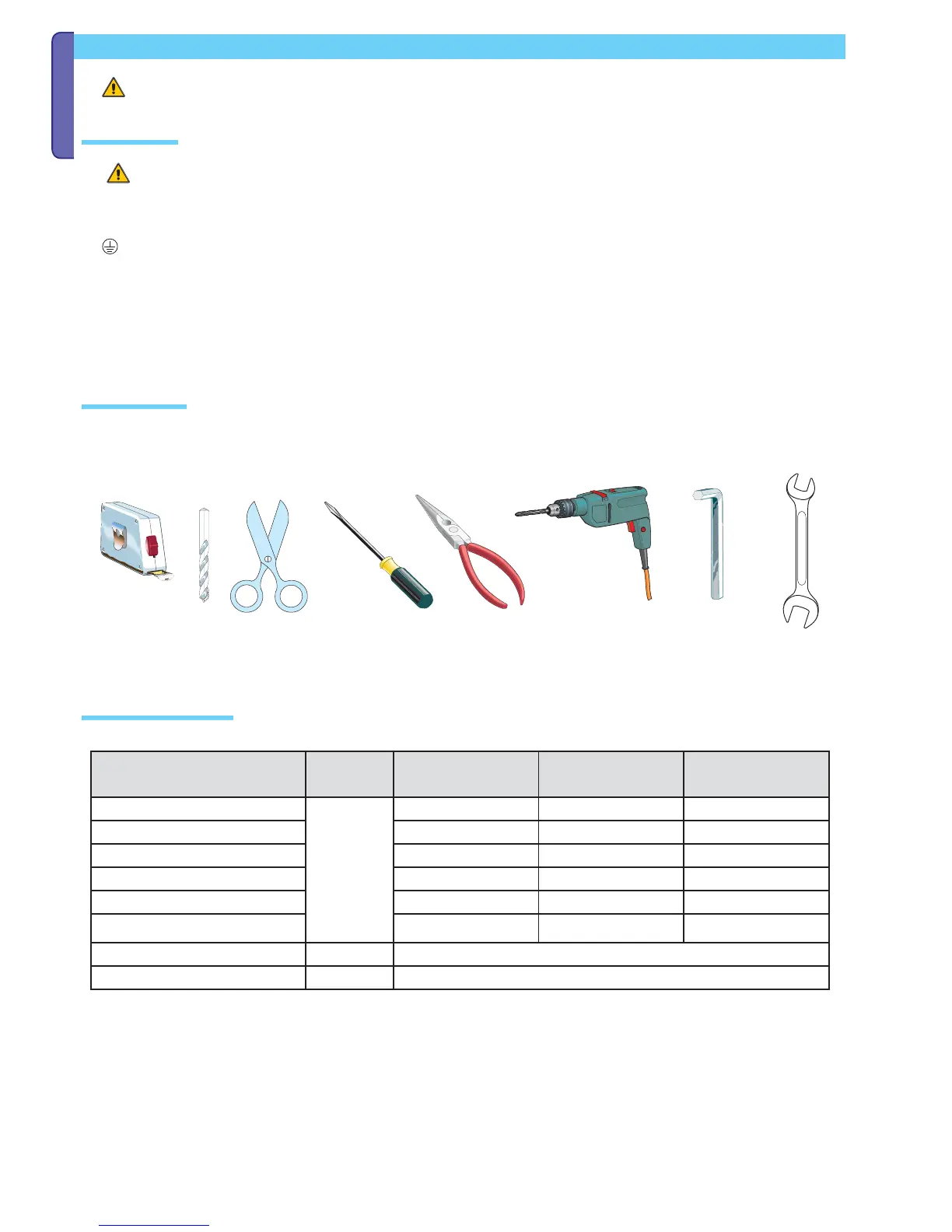
Tools and equipment
Make sure you have all the tools and materials needed to carry out the installation in total safety and in accordance with current regulations. The figure
shows some examples of the tools needed by installers.
System feasibility
Preliminary checks