Do you have a question about the Canon imageRUNNER 5065 series and is the answer not in the manual?
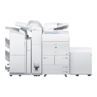
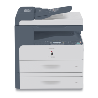
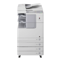
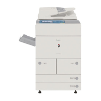
Details the system configurations with various accessories for pickup, delivery, printing, and transmission.
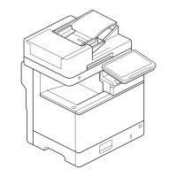
Lists names of parts, external views, cross-sections, and usage of the machine.
Covers pre-installation checks including installation space, accessory combination, and contents verification.
Provides procedures for unpacking the machine and installing various components like the scanner, fixing assembly, and pickup assembly.
Details how to check network connectivity using Ping command and remote host address.
Offers troubleshooting steps for network connection failures, including cable checks and loopback/local host address checks.
Covers installation procedures and notices for the card reader accessory.
Provides instructions for checking contents and installing the original holder.
Details checking contents and installation procedures for the reader heater.
Covers checking components, power-off procedures, and installation of the cassette heater.
Details checking parts to install for the deck heater unit.
Describes checking parts to install for the large deck heater.
Provides points to keep in mind during installation and checks for the voice guidance kit.
Explains the functional construction and wiring diagram of the major PCBs.
Details basic sequences of operation at power-on and during copying/printing.
Describes the construction and mechanisms of the main controller block.
Details the construction of the electrical circuitry of the main controller.
Explains the start-up sequence, including overview and detailed steps.
Outlines the shut-down sequence to prevent HDD damage.
Details the image processing flow, module construction, and specific processing steps.
Illustrates the flow of image data for various functions like copy, box, SEND, FAX, and PDL.
Provides procedures for replacing major parts of the main controller.
Details specifications, controls, functions, major components, and control system construction.
Explains basic sequences of operations and response to start key press.
Covers control of scanner drive system, enlargement/reduction, scanning lamp, original size detection, and dirt sensor.
Provides detailed procedures for replacing components like CCD unit, copyboard glass, scanning lamp, and PCBs.
Details specifications, controls, functions, major components, and control system construction.
Explains the basic sequence of operation for laser exposure.
Covers control of laser activation timing, intensity, and scanner motor.
Provides procedures for removing and replacing the laser scanner unit.
Details the functions and methods of the machine's image formation system.
Outlines the 8 steps of the machine's image formation process.
Describes the basic sequence of operation at power-on and time of printing.
Explains functions and controls associated with potential control.
Covers control of pre-exposure LED and primary charging mechanism.
Details overview, detection of collecting toner case state, and drum/separation claw bias control.
Covers control of the developing assembly drive, bias, and toner level.
Explains transfer charging mechanism and controlling output to suit environment.
Details separation charging mechanism and correcting output to suit environment and drum surface potential.
Provides procedures for replacing various parts of the image formation system.
Details specifications, rollers/sensors arrangement, and pickup control system outlines.
Describes basic sequences for pickup from right deck, cassette 3, and pickup retry operations.
Covers jam detection outlines, history, delay jams, and stationary jams.
Details lifter operation, paper presence detection, and paper level detection for cassettes.
Covers pickup operation and paper size detection for the manual feed tray.
Details lifter operation, paper presence/level detection, and size identification for decks.
Provides an outline and control system for the registration unit.
Explains paper movement for duplex printing and through-path operations.
Details reversal delivery operation for face-up and face-down modes.
Provides detailed procedures for replacing various pickup and feeding system components.
Details specifications, controls, mechanisms, major components, and IH fixing method.
Explains various start-up modes, power save, sleep, copying/printing, and down sequences.
Covers fixing drive system, cleaning mechanisms, and paper passage detection.
Details error detection using thermistors, thermal switches, and general error codes.
Provides procedures for replacing fixing/feeding assembly, fixing unit, pressure roller, and fixing rollers.
Covers overview, LCD indication processing, contrast adjustment, and control panel CPU functions.
Details the soft counters used for tracking print jobs.
Describes fan arrangement, functions, and error codes.
Explains power supply distribution, rated outputs, and protection functions.
Provides detailed procedures for replacing external covers and internal assemblies.
Covers checking operating environment, network setup, SMS login, application management, specifications, and licensing.
Details application operation modes, service center URL, communication tests, logs, and e-RDS settings.
Lists parts that require periodical replacement and how to check replacement timing.
Details durable parts and consumables that may need replacement based on estimated lives.
Provides a basic procedure for scheduled servicing and periodical servicing charts.
Details cleaning procedures for various components like toner blocking sheets, cleaner scraper, and photosensitive drum.
Covers pre-checks, copier/printer unit checks, and potential system checks.
Details standards for image position and adjustments for side registration and margins.
Covers procedures after replacing reader controller PCB, CCD unit, copyboard glass, reading glass, and scanning lamp.
Procedure for replacing the scanner unit.
Details routing of charging wire, grid, and mounting of cleaning blade.
Covers applying grease, adjusting nip width, fixing web solenoid, and inlet guide.
Lists PCBs, connectors, variable resistors, LEDs, and check pins.
Details points to note when mounting pickup/separation rollers and adjusting pressures and positions.
Covers checks on site environment, originals, copyboard, charging, developing assembly, paper, and replaced parts.
Details malfunction/faulty detection and general troubleshooting steps.
Lists clutches, solenoids, motors, fans, sensors, switches, lamps, heaters, PCBs, and connectors.
Lists all error codes and their descriptions.
Provides detailed explanations and remedies for specific error codes.
Details error codes related to the SEND function and results of self-diagnosis.
Lists jam codes for machine proper, finisher, and ADF.
Provides a table of alarm codes and their descriptions.
Explains service mode screen configuration, entry, exit, backup, and initial screen.
Details the COPIER and FEEDER lists for status display.
Provides an outline and lists for R-CON, FEEDER, SORTER, and BOARD.
Covers adjustment modes for COPIER, FEEDER, and SORTER.
Details functional modes for COPIER, FEEDER, and SORTER.
Covers settings for COPIER, FEEDER, SORTER, BOARD, and other options.
Explains how to generate test prints for various modes like COPIER, FEEDER, and NETWORK.
Details counter lists for COPIER, PICKUP, FEEDER, JAM, MISC, and PRDC-1.
Provides an outline of machine upgrading and the service support tool.
Covers registering system software and making necessary connections.
Details procedures for formatting all partitions or selected partitions.
Covers downloading system, RUI, language, SDICT, MEAPCONT, KEY, TTS, BOOT, Dcon/Rcon, G3 FAX, and backup data.
Lists special tools and solvents/oils required for service.
| Print Resolution | 1200 x 1200 dpi |
|---|---|
| Copy Resolution | 600 x 600 dpi |
| Scan Resolution | 600 x 600 dpi |
| Functions | Print, Copy, Scan |
| Print Speed (B/W) | 65 ppm |
| Warm-up Time | Less than 30 seconds |
| Paper Sizes | Letter, Legal, Executive, Custom sizes |
| Duplex Printing | Standard |
| Copy Speed | Up to 65 ppm (Letter) |
| Multiple Copy | Up to 999 copies |
| Zoom | 25-400% |
| Scan Destinations | |
| Interface | USB 2.0, Ethernet |
| Network Connectivity | Ethernet (10/100Base-TX) |
| Operating System Compatibility | Windows, Mac |
| Power Consumption | 1.5 kW |
| Display | Touch-screen LCD |