Chapter 7
7-31
- The charging wire must be fitted in the V-groove of the charging wire
positioning plate.
9) Attach a cushion in front of the charging wire (except the primary
charging assembly).
10) Attach the shield plates (left, right).
For other charging assemblies, attach the 2 covers.
11) Attach the wire cleaner. At this time, make sure the orientation of the
wire cleaner.
12) Wipe the charging wire with lint-free paper moistened with alcohol
solutions.
7.10.20.3 Routing Grid for Primary Charging Assembly
0015-9968
iR5065 / iR 5055 / iR5075 / / /
1) Loosen the 2 screws used to secure the left and right shielding plates in
place.
2) Loosen the 3 screws used to secure the motor unit at the front in place.
F-7-102
3) Loosen the screw, and move it in the direction of the arrow indicated
below; then, temporarily tighten it in place.
4) Free a length of about 5 cm of the charging wire (0.1 mm in diameter)
from the charging wire reel, and form a loop at its end with a diameter of
about 2 mm.
F-7-103
MEMO:
To form a loop, wind the charging wire around a hex key once, and turn the
hex key 3 to 4 times; then, twist the charging wire.
5) Cut the twisted charging wire (excess) with nippers.
6) Hook the loop on the stud A.
7) After routing the wire for 31 runs, lead it through the section B, and give
it a half turn; then, put it between the washer and the monitor unit, and
wind it once around the screw (clockwise), and secure it in place with the
screw.
F-7-104
8) Cut the excess of the charging wire with nippers.
9) Tighten the screw loosened in the step 3.
Keep tightening until the tension of the grid wire is even. Be sure to pay
attention to avoid deformation (deflection) of the charging assembly (as
by tightening the screw at the front of the left/right shielding plate early).
10) Tighten the screws loosened in the step 1 and 2.
11) Wipe the grid wire with lint-free paper moistened with alcohol solutions.
Make sure the followings:
- The grid wire must not be bent or twisted.
- The wires are laid at equal intervals. (The grid wire must be fitted in the
groove of the block.)
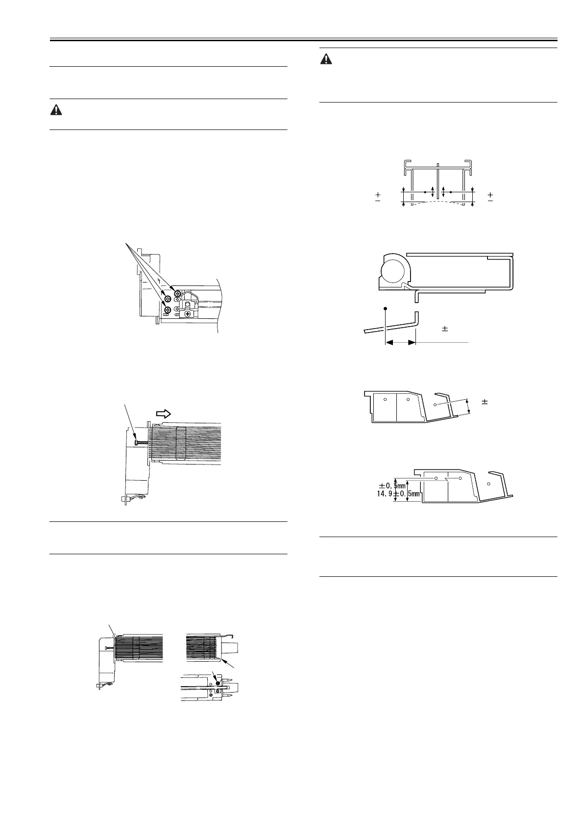
7.10.20.4 Adjusting Height of Charging Wire
0015-9969
iR5065 / iR 5055 / iR5075 / / /
[1] Primary charging wire
F-7-105
Height of the charging wire
<Tolerance> +/-1 mm
[2] Pre-transfer charging wire
F-7-106
Height of the charging wire
<Tolerance> No height adjusting mechanism
[3] Transfer charging wire
F-7-107
Height of the charging wire
<Tolerance> +/-2 mm
[4] Separation charging wire
F-7-108
Height of the charging wire
<Tolerance> +/-2 mm
MEMO:
The height (position) of the primary charging wire and the transfer charging
wire can be adjusted by turning the screw at the back of the charging assem-
bly. A single turn changes the position of the charging wire by about 0.7 mm.
Screws
Screw
Stud A
Screw
B
7.5
1.5
0 mm
7.5
1.5
0 mm
10.06 0.3 mm
9.5 0.5mm
6.0
 Loading...