Chapter 8
8-26
8.10 Parts Replacement Procedure
8.10.1 Pickup Roller
8.10.1.1 Before Removing the Pickup Roller
0015-4961
iR5065 / iR 5055 / iR5075 / / /
1) Remove the right deck pickup assembly. (page 8-
30)Reference[Removing the Right Deck Pickup Assembly]
2) Remove the cassette pickup assembly. (page 8-26)
Reference[Removing
the Cassette 3/4 Pickup Assembly]
3) Remove the left deck pickup assembly. (page 8-
30)Reference[Removing the Left Deck Pickup Assembly]
8.10.1.2 Removing the Pickup Roller
0015-4965
iR5065 / iR 5055 / iR5075 / / /
1) Remove the pickup roller [2] in the direction of the arrow.
- 2 resin E-rings [1]
F-8-52
8.10.1.3 Points to Note When Mounting the Pickup Roller
0016-0018
iR5065 / iR 5055 / iR5075 / / /
Å°The direction of the mounting pickup roller
The pickup roller may be mounted by reversing the steps used to remove it;
however, be sure to keep the following in the mind.
- The roller used at the front and the rear of the machine is not compatible.
- When mounting the pickup roller used at the front of the machine [1],
make sure the round mark [2] and the punch mark [3] found on the side
of the roller are toward the front of the machine.
F-8-53
- When mounting the pickup roller used at the rear of the machine [1],
make sure the punch mark [2] is at the rear of the machine.
F-8-54
8.10.2 Cassette Pickup Assembly
8.10.2.1 Removing the Cassette 3/4 Pickup Assembly
0015-4967
iR5065 / iR 5055 / iR5075 / / /
The steps to remove the cassette 3 pickup assembly and the cassette 4 pickup
assembly are the same.
1) Slide out the cassette 3/4.
2) Open the right door unit (rear).
An attempt to remove the pickup assembly without removing the cassette
causes the lifter get trapped and may hold the pickup assembly from sliding
out.
3) Disconnect the connector [3].
- 1 screw [1]
- 1 connector cover [2]
4) Remove the cassette 3/4 assembly [5].
- 3 screws [4]
F-8-55
8.10.3 Cassette Pickup Motor
8.10.3.1 Before Removing the Cassette 3/4 Pickup Motor
0015-4968
iR5065 / iR 5055 / iR5075 / / /
1) Remove the charger unit (this step is necessary only for iR5075 for Japan).
(page 10-20)
Reference[Removing the Charger unit]
2) Remove the rear cover (upper). (page 10-11)
Reference[Removing the
Rear Cover (Upper)]
3) Remove the rear cover (lower). (page 10-11)
Reference[Removing the
Rear Cover (Lower)]
4) Remove the main controller box cover.(page 10-
15)Reference[Removing the Main Controller Box Cover]
5) Remove the right cover (upper rear).(page 10-10)
Reference[Removing
the Right Cover (Upper Rear)]
6) Remove the main controller box. (page 4-13)
Reference[Removing the
Main Controller Box]
7) Remove the right cover (lower rear). (page 10-10)
Reference[Removing
the Right Cover (Lower Rear)]
8) Remove the collecting toner bottle holder. (page 5-
28)Reference[Removing the Collecting Toner Bottle Holder]
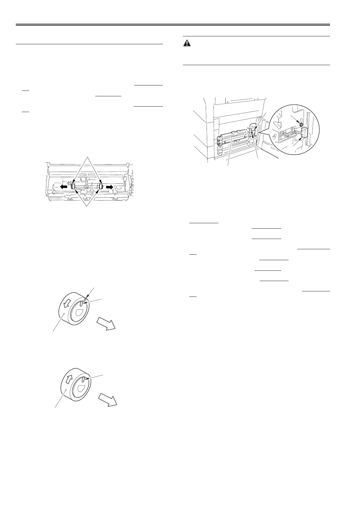
8.10.3.2 Removing the Cassette 3/4 Pickup Motor
0015-4974
iR5065 / iR 5055 / iR5075 / / /
1) Remove the harness [1] from the 9 wire saddles.
- 10 connectors
2) Remove the motor driver PCB mounting base [3].
- 4 screws [2]
[1]
[2]
Direction of
rotation
Front side of
the machine
[1]
[2]
[3]
Direction of
rotation
Rear side of
the machine
[1]
[2][2]
[1]
[2]
[5]
[4]
[3]
 Loading...