Chapter 7
7-15
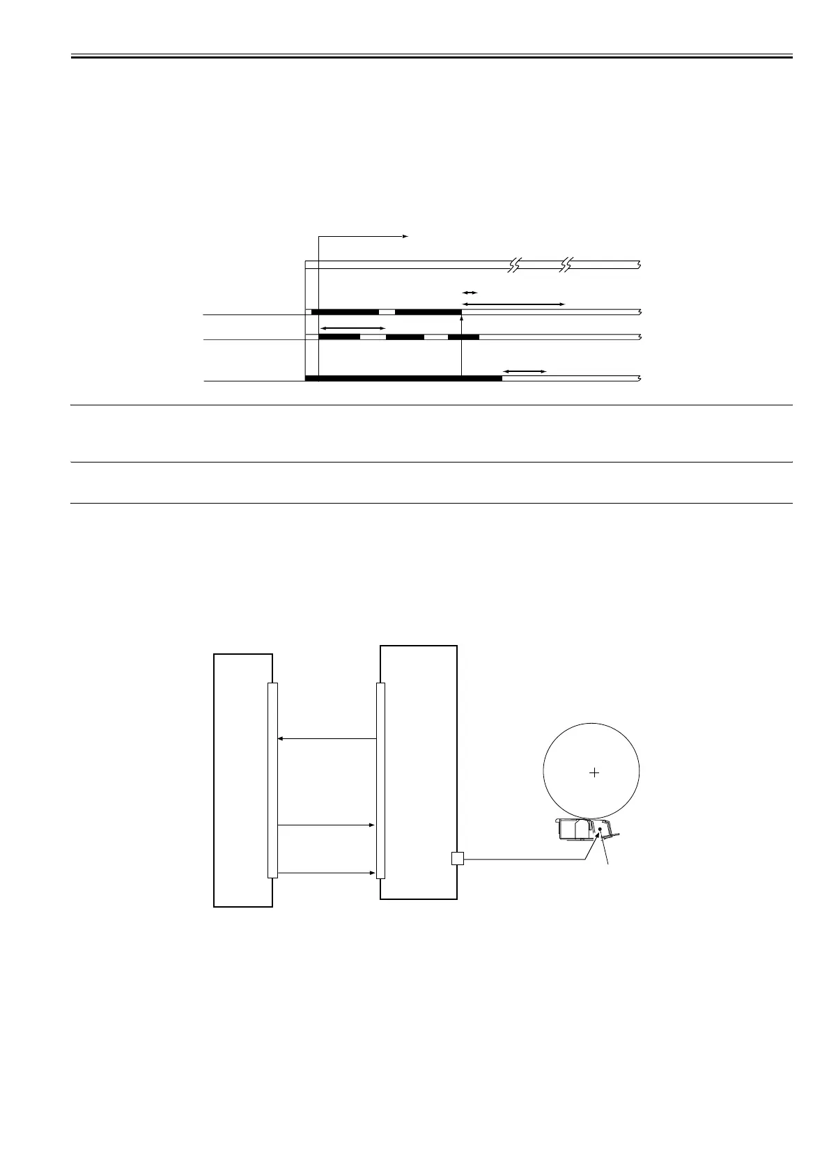
Toner Supply Sequence
The toner inside the developing assembly is monitored by the developing assembly toner level sensor (TS1); when the toner inside the developing assembly falls
below a specific level, the developing assembly toner level signal goes '0' so that the DC controller PCB recognizes it.
If the DC controller PCB detects the developing assembly toner level signal for 0.3 sec or more, it generates the hopper motor drive signal so that the hopper as-
sembly will start supplying toner.
When the toner inside the developing assembly reaches a specific level and, as a result, the developing assembly toner level signal remains '1' for 0.7 sec or more,
the hopper supply motor stops.
When the toner inside the hopper drops below a specific level, the hopper toner level detection signal goes '0'. If the signal remains '0' when the toner supply motor
has been turned on and off 20 times after the detection of the signal state by the DC controller, the machine issues a message of bottle exchange.
Total rotating time reaches 60 seconds after the toner sensor in the developing assembly senses no toner, the machine issues a method of exchanging bottles and
stops the ongoing printing operation.
When the toner bottle is replaced, the hopper supply motor and the stirring motor are turned on, and the developing assembly inside toner level detection signal
goes '1', the machine resets the message of bottle exchange and resumes printing.
F-7-26
ERROR CODE:
E020-0000
Indicated while the output of the inside hopper toner level sensor (TS2) points to the presence of toner and the output of the developing assembly toner level sensor
(TS1) inside the developing assembly points to the absence of toner for 120 sec or more.
7.8 Transfer Mechanism
7.8.1 Transfer Charging Mechanism
7.8.1.1 Overview
0015-4502
iR5065 / iR 5055 / iR5075 / / /
The following items are associated with the transfer charging control system:
1. controlling the DC bias constant current
2. controlling the output to suit the environment (fuzzy control)
The following shows the construction of the transfer charging control system:
F-7-27
The following signals are associated with the transfer charging control mechanism:
[1] Transfer charging leakage detection signal; when the current is too high or too low, '0'
[2] Transfer charging current control signal; used to control the transfer current generated by the high-voltage PCB
[3] High-voltage remote signal; turns on/off the transfer current output
7.8.1.2 Controlling the Output to Suit the Environment (fuzzy control)
0015-4503
iR5065 / iR 5055 / iR5075 / / /
The transfer charging current is optimized to suit the environment (i.e., reading of the environment sensor).
Toner supply sequence start
Toner supply
Hopper supply motor
(M10)
Developing assembly
toner level sensor (TS1)
Inside hopper
toner level sensor (TS2)
Supply
Supply
If 120 sec or more,
'020-0000' is indicated
total activation (ON) time of hopper
stirring motor reaching 60 sec, message of
method of exchanging bottles -> print suspension.
1 cycle (5 sec max.)
toner supply motor driven for 20 cycles,
message of exchanging bottles.
DC controller PCB
High-voltage PCB
HVT_TRANSFER [2]
TRANSFER-LEAK-
DETECT [1]
Transfer charging wire
HVT-REMOTE [3]
J4502
J102A
 Loading...