Chapter 6
6-3
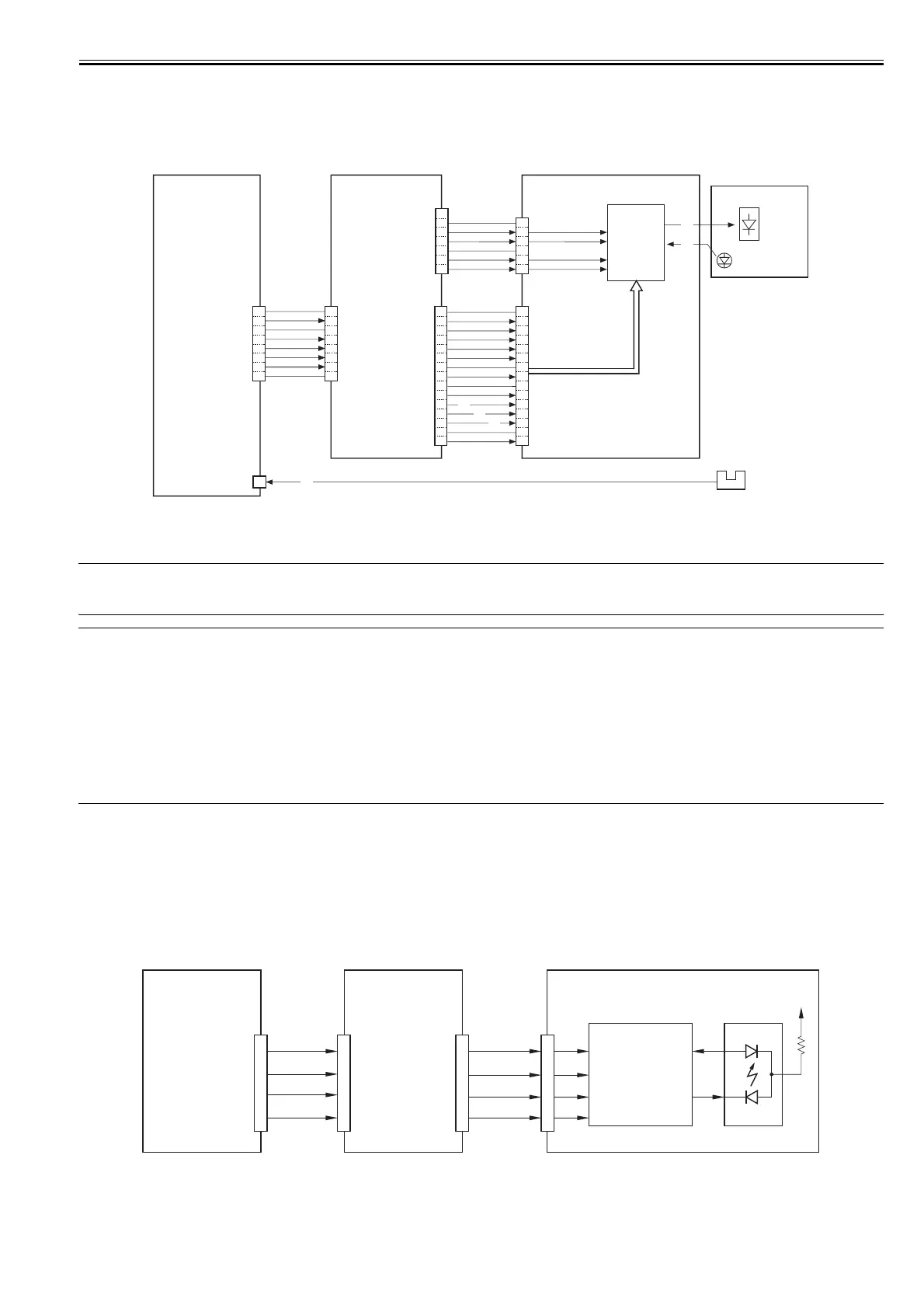
The various signals have the following meanings and functions:
[1] sample laser activation signal; for each scan, it turns on the laser for sampling of light intensity (for imaging)
[2] laser activation enable signal; after the Start key has been pressed, it goes '0'when the laser is ready for activation.
[3] laser write start signal; when paper reaches the laser write start sensor (PS28) mounted in front of the registration roller, the machine starts laser write operation.
[4] the machine monitors the intensity of laser light upon its activation (for sampling), and feeds the appropriate value to the laser drive circuit.
[5] the machine controls the output so that the value that has been fed and the reference value from the DC controller are identical.
[6] laser intensity reference signal; it serves as the laser activation reference (determined as a result of potential control by the DC controller).
F-6-4
MEMO:
- The laser power is adjusted automatically when the laser unit is replaced.
- When the manual feed tray is used as the source of paper, the write operation starts when the registration paper sensor (PS29) detects paper.
SERVICE MODE:
DISPLAY> DPOT> LLMT
indicates the laser power voltage control value for copier imaging.
DISPLAY> DPOT> LPOWER-P
indicates the result of potential control for the laser intensity used during printer (PDL) imaging.
DISPLAY> DPOT> LPOWER-C
indicates the result of potential control for the laser intensity used during copier imaging.
DISPLAY> MISC> LPOWER
indicates the laser intensity in real time.
ADJUST> LASER> PVE-OFST
used to adjust the laser incident point.
FUNCTION> LASER> POWER
used to turn on laser light.
6.3.2.2 APC Control
0015-4428
iR5065 / iR 5055 / iR5075 / / /
The machine executes APC control so that the laser light will remain at a constant level by adjusting the output of the laser diode mounted on the laser driver.
The control mechanism takes place on the DC control PCB.
The DC controller sends the laser control signal (LD1: CTL0=0, CTL1=1, CTL2=0; LD2: CTL0=1, CTL1=0, CTL2=0; both APC-SEL=0) to the laser driver IC
on the laser driver PCB.
In response, the laser driver IC sets APC mode, and forces the laser diode (LD) to emit light.
While all this is under way, the laser driver IC monitors the laser diode (LD) by means of a photo diode (PD), and adjusts the output of the laser diode unit so that
the intensity is at a specific level.
F-6-5
DC controller
PCB
Laser driver PCB
J1408
J1411
J113
J122
J1401
J4500
LWRPD
J5501
Laser block
Laser
Photo
Monitor
Laser
driver
Circuit
B2
Laser write
Start sensor
(PS28)
Laser unit
Video PCB
7
6
5
4
3
2
1
GND
GND
VD1N
VD2P
GND
VD2N
VD2P
1
2
3
4
5
6
1
2
3
4
5
6
7
8
GND
SDCLK
GND
SCLK
DIO
DIR
CSU
GND
1
2
3
4
5
6
7
8
15
14
13
12
11
10
9
8
7
6
5
4
3
2
1
15
14
13
12
11
10
9
8
7
6
5
4
3
2
1
GND
(N.C.)
CSU
DIR
DIO
SCLK
GND
SDCLK
GND
CTL2
[2] CTL1
[1] CTL0
APC-SEL
GND
+5V
[6]
[4]
[5]
[1]
[2]
[3]
Laser
Driver
IC
5V
PD
LD
J101
APC-SEL
CTL0
CTL1
CTL2
APC-SEL
CTL0
CTL1
CTL2
J121
DC controller
PCB
Video PCB
Laser Driver PCB
 Loading...