Chapter 10
10-22
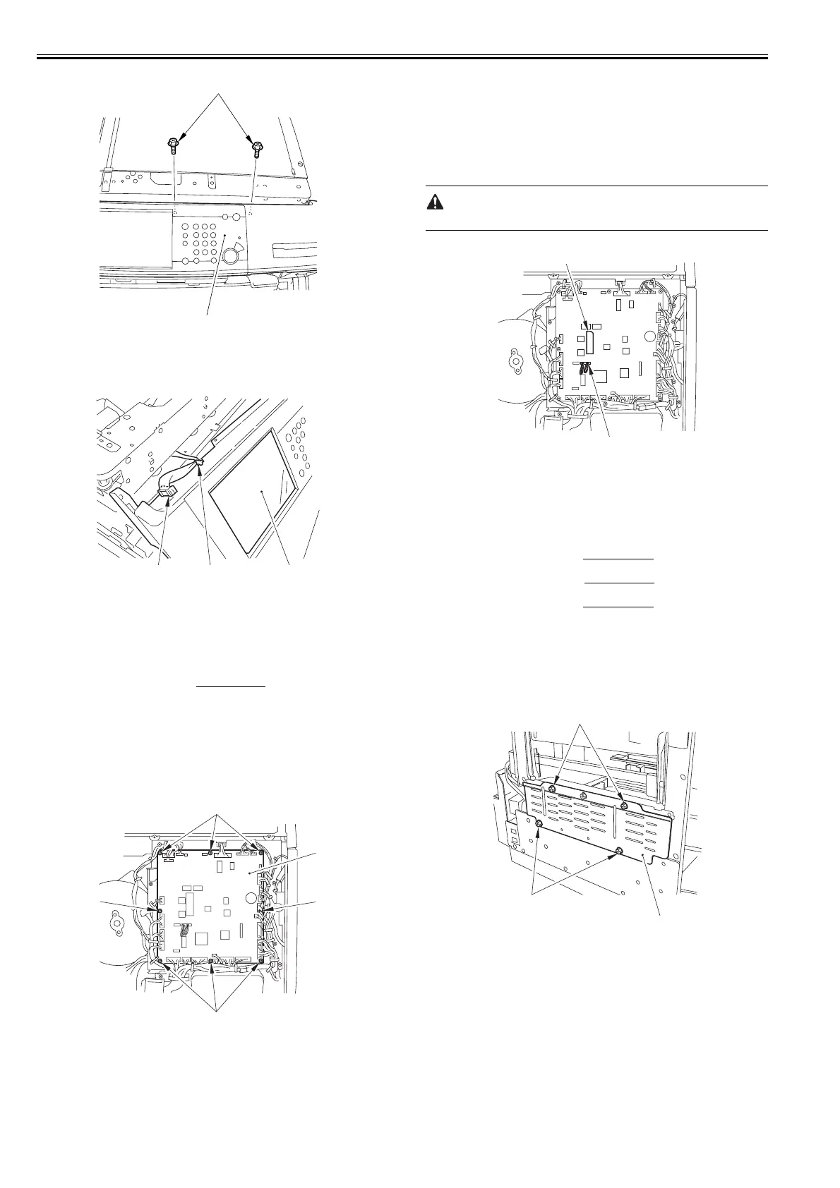
F-10-70
3) Shift the control panel [3] together with the cover, and remove the use
band [1] and disconnect the connector [2]. Then, remove the control panel
[3].
F-10-71
10.5.12 DC Controller PCB
10.5.12.1 Before Removing DC Controller PCB
0015-5119
iR5065 / iR 5055 / iR5075 / / /
1) Detach the rear cover (upper). (page 10-11)
Reference[Removing the
Rear Cover (Upper)]
10.5.12.2 Removing DC Controller PCB
0015-6585
iR5065 / iR 5055 / iR5075 / / /
1) Remove the DC controller PCB [2].
- 28 connectors
- 8 screws [1]
F-10-72
10.5.12.3 When Replacing DC Controller PCB
0015-9987
iR5065 / iR 5055 / iR5075 / / /
Be sure to perform the followings when replacing the DC controller PCB.
1) Enter the latest values for the service mode indicated on the label [1] on
the back of the front cover with the service mode.
2) Enter the values indicated on the label [1] of the new PCB using the
following service mode items:
COPIER> ADJUST> HV-TR> D-PRE-TR
COPIER> ADJUST> HV-TR> D-HV-TR
COPIER> ADJUST> HV-SP> D-HV-SP
COPIER> ADJUST> DEVELOP> D-HV-DE
3) Move the J303 shorting connector [2] on the PCB from the existing to the
new PCB.
Make sure to connect the shorting connector. Otherwise, E004 occurs.
F-10-73
10.5.13 Printer Power Supply PCB
10.5.13.1 Before Removing Printer Power Supply PCB
0015-5122
iR5065 / iR 5055 / iR5075 / / /
1) Detach the left cover (upper). (page 10-10)
Reference[Removing the
Left Cover (Upper)]
2) Detach the left cover (middle). (page 10-12)
Reference[Removing the
Left Cover (Middle)]
3) Detach the left cover (lower). (page 10-11)
Reference[Removing the
Left Cover (Lower)]
10.5.13.2 Removing Printer Power Supply PCB
0015-5125
iR5065 / iR 5055 / iR5075 / / /
1) Detach the shield plate [2].
- 4 screws [1]
F-10-74
2) Detach the power supply cover [2].
- 9 screws [1]
[1]
[2]
[1][2]
[3]
[1]
[1]
[1]
[1]
[2]
[1]
[2]
[1]
[1]
[2]
 Loading...