Chapter 9
9-20
1) Remove the pressure roller assembly [1]. Place the removed pressure
roller assembly temporarily on the paper.
F-9-33
2) Remove the pressure roller assembly.
- 2 E-rings at the both end [1]
- 2 bearings [2]
F-9-34
As aged, the rubber surface of the pressure roller may be discolored by heat.
This change, however, will not affect its performance or output images. Fur-
ther, the physical properties of the roller may develop wrinkles on the roller
surface. The wrinkles will be smoothed under heat and not affect the per-
formance, so that the replacement is not required.
9.5.4 Upper Fixing Roller
9.5.4.1 Before Removing the Fixing Roller
0015-7188
iR5065 / iR 5055 / iR5075 / / /
1) Detach the duplexing feed front cover. (page 10-
12)Reference[Removing the Duplexing Feed Front Cover]
2) Slide out the fixing/feeding unit. (page 9-18)
Reference[Removing the
Fixing/Feeding unit]
3) Detach the fixing front cover. (page 10-14)
Reference[Removing the
Fixing Front Cover]
4) Detach the fixing/feeding unit front cover. (page 10-
13)Reference[Removing the Fixing/Feeding Unit Front Cover]
5) Detach the fixing/feeding unit middle cover. (page 10-
13)Reference[Removing the Fixing/Feeding Unit Middle Cover]
6) Detach the fixing upper cover. (page 10-13)
Reference[Removing the
Fixing Upper Cover]
7) Remove the fixing drive assembly. (page 10-20)
Reference[Removing
the Fixing Drive Assembly]
8) Remove the fixing upper unit. (page 9-19)
Reference[Removing the
Fixing Upper Unit]
9) Remove the fixing web. (page 9-31)
Reference[Removing the Fixing
Web]
9.5.4.2 Removing the Fixing Roller
0015-5047
iR5065 / iR 5055 / iR5075 / / /
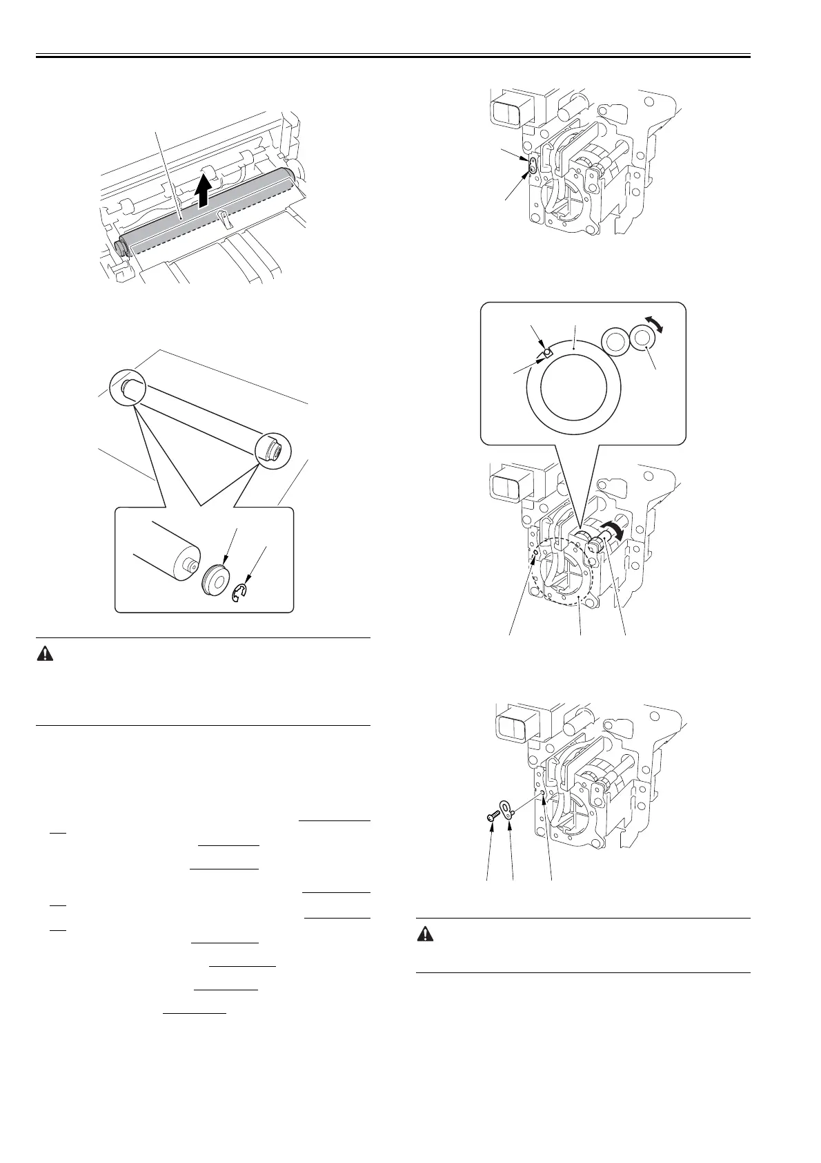
1) Remove 1 screw [1] and the pin [2]. The screw and pin removed here will
be used in the step 6).
F-9-35
2) Rotate the shutter drive gear [1] by finger so that the shutter gear [2]
rotates until the cut-off [3] of the shutter gear matches the hole in the plate
[4].
F-9-36
3) Fit the pin removed in the step 1) into the hole [2], then fix with 1 screw
[3] in place.
F-9-37
The pin should be fit back in the initial position after completing the forego-
ing steps and before mounting the fixing upper unit on the machine.
4) Remove 2 screws [2] that fix the AC connector support plate [1].
[1]
[1]
[2]
[1]
[2]
[1]
[2]
[3]
[4]
[1][2][4]
[1] [2][3]
 Loading...