Chapter 14
14-20
<Tolerance> +/-1 mm
[2] Pre-transfer charging wire
F-14-46
Height of the charging wire
<Tolerance> No height adjusting mechanism
[3] Transfer charging wire
F-14-47
Height of the charging wire
<Tolerance> +/-2 mm
[4] Separation charging wire
F-14-48
Height of the charging wire
<Tolerance> +/-2 mm
MEMO:
The height (position) of the primary charging wire and the transfer charging
wire can be adjusted by turning the screw at the back of the charging assem-
bly. A single turn changes the position of the charging wire by about 0.7 mm.
14.5.5 Mounting Cleaning Blade
0015-9970
iR5065 / iR 5055 / iR5075 / / /
When mounting the cleaning blade, be sure that the side with the marking [1]
will be the face.
1) Push in the cleaning blade [2] until it butts slightly against the rear.
F-14-49
2) Tighten the 5 screws [3] lightly, and stop to turn them when resistance is
felt.
3) Turn the screws tightened lightly in the step 2 about 20 to 30 degrees in
the order indicated below, and tighten them fully.
F-14-50
After mounting the cleaning blade, check that the edge of the blade is not ex-
tremely bent.
Further, be sure to clean the groove in the blade support plate before mount-
ing the blade, as toner or the like in the groove can be the cause the bending
of the blade. ÅB
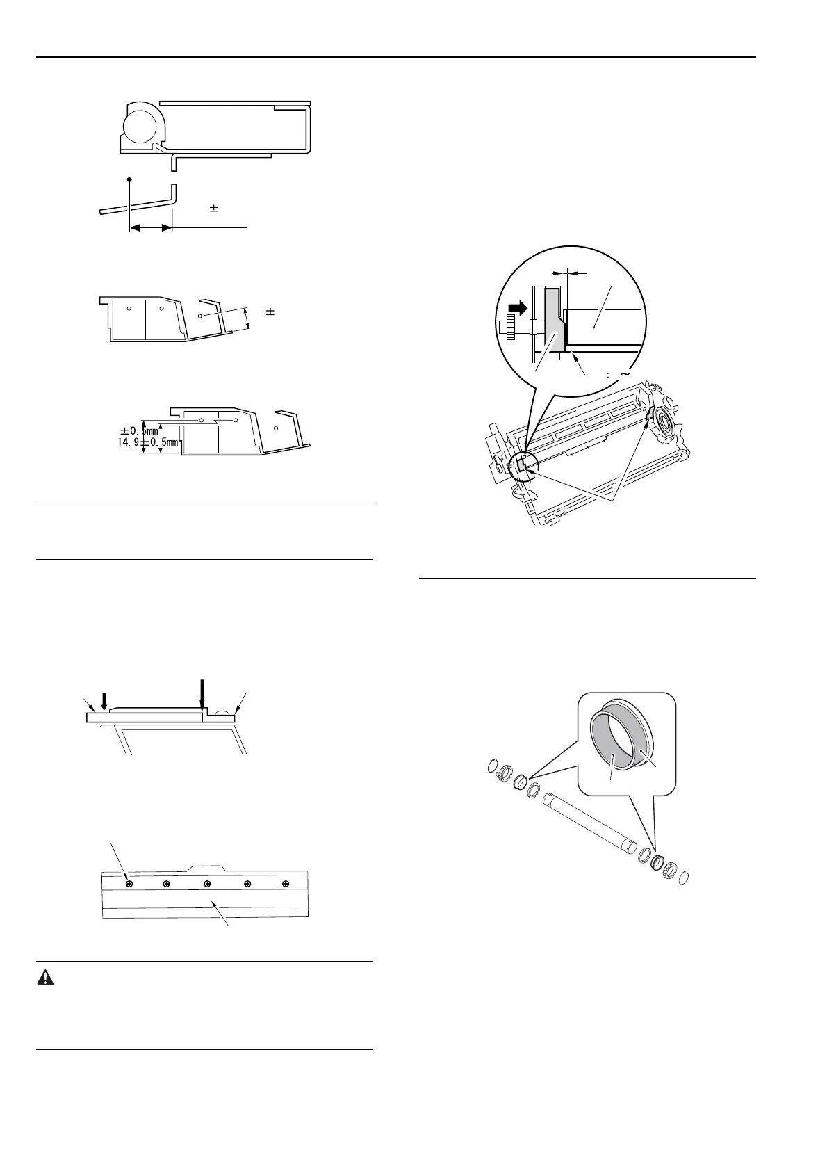
14.5.6 Removing Side Seal
0015-9972
iR5065 / iR 5055 / iR5075 / / /
1) Remove the old side seal.
2) Mount the new side seal [1] to the cleaner housing where indicated (both
ends).
At this time, be sure that the edge of the side seal is positioned as follow:
- When replacing the side seal [1] at the front, push the magnet roller [2]
toward the rear, and then, make sure that the inner end of the side seal is
within the area [3] of the washer.
- When replacing the side seal [1] at the rear, push the magnet roller [2]
toward the front, and then, make sure that the inner end of the side seal is
within the area [3] of the washer.
3) The bottom end of each side seal [1] must be 0 to 0.5 mm from the corner
of the cleaner housing; i.e., point of reference [4].
4) Attach the side seal [1] at the front and the rear to the cleaner housing
while making sure its position is as indicated.
F-14-51
14.6 Fixing System
14.6.1 Applying Grease After Replacing the Fixing Roller
0015-9974
iR5065 / iR 5055 / iR5075 / / /
- About 20mg of grease (Molykote HP-300; CK-8012) should be applied
to the inner [1] and the outer surfaces [2] of the bushing until the white
coat covering is formed uniformly. If this undone, the noise (squeaking)
may occur.
F-14-52
- Applied grease may be transferred from the bushing to the fixing roller
ends [1] when mounting; be sure to wipe it off when this happens.
10.06 0.3 mm
9.5 0.5mm
6.0
No gap
Blade retaining plate
[2]
[1]
Order of tightening
5
[3]
3124
0 0.5mm
[3]
[2]
[1]
[4]
[1]
[2]
[1]
 Loading...