Chapter 4
4-13
4.7 Parts Replacement Procedure
4.7.1 Main Controller Box
4.7.1.1 Before Removing the Main Controller Box
0015-6362
iR5065 / iR 5055 / iR5075 / / /
1) Detach the rear cover (upper). (page 10-11)
Reference[Removing the
Rear Cover (Upper)]
2) Detach the main controller box cover. (page 10-
15)Reference[Removing the Main Controller Box Cover]
3) Detach the right cover (upper rear). (page 10-10)
Reference[Removing
the Right Cover (Upper Rear)]
4.7.1.2 Removing the Main Controller Box
0015-4788
iR5065 / iR 5055 / iR5075 / / /
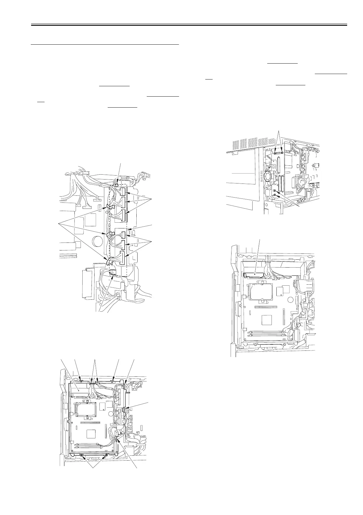
1) Disconnect the 7 connectors [4] of the video PCB [1].
- 3 Wire saddle [2] (to free the harness)
- 1 Reuse band [3]
F-4-21
2) Disconnect all the connectors of the main controller PCB, and detach the
main controller box [3].
- 5 Edge saddle [1] (to free the harness)
- 4 Screw [2]
F-4-22
4.7.2 Main Controller PCB
4.7.2.1 Before Removing the Main Controller PCB
0015-6366
iR5065 / iR 5055 / iR5075 / / /
1) Detach the rear cover (upper). (page 10-11)
Reference[Removing the
Rear Cover (Upper)]
2) Detach the main controller box cover. (page 10-
15)Reference[Removing the Main Controller Box Cover]
3) Detach the right cover (upper rear). (page 10-10)
Reference[Removing
the Right Cover (Upper Rear)]
4.7.2.2 Removing the Main Controller PCB
0015-4789
iR5065 / iR 5055 / iR5075 / / /
1) Remove the 4 screws [1].
F-4-23
2) Detach the reader relay PCB [1] from the main controller PCB.
F-4-24
3) Detach the Video PCB unit [3].
- Screw [1] 2pc.
- Connector [2] 7pc.
[1]
[2]
[3]
[4]
[4]
[4]
[1]
[2]
[1] [1]
[1]
[2] [2][3]
[1]
[1]
[1]
 Loading...