Chapter 5 Fault Isolation Tool Collection
4-21
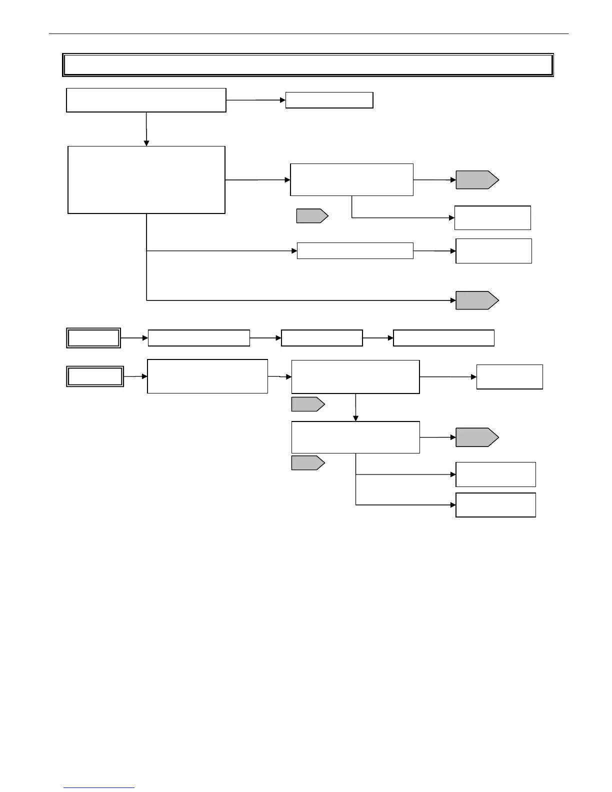
T17 Electrical ejection fault isolation tool
Replace the main controller Replace the printhead Replace the carriage unit
Flow 1
Check flat cable ③a for proper connection to
the main controller
Reinsert the connector
Confirm that the connector is locked,
and is not inserted slantwise.
Abnormal
Normal
Flow 1
Flow 2
Normal
Replace the carriage
unit (*1)
iPF5000 Series
With the printer switched off, do the following:
- Clean head contact pin ⑦ with a blower.
- Remove and reinsert the head (three
times).
* After unlocking the carriage in T14, pull it
out and then remove and reinsert the head.
Continuity check
Check for a disconnection between
flat cable ③a and contact pin ⑦
Abnormal
iPF700 Series
Replace the carriage relay PCB
iPF800/iPF8000 Series
Replace the carriage
unit (*2)
The iPF700 does not allow continuity checking between ③a and ⑦ (because such checking
requires the intervention of the IC on the carriage relay PCB)
T18
Continuity check
Check for a disconnection between
a and b of flat cable (long) ③
Disconnected
Check flat cables ③b and ⑤a for
proper connection to carriage
relay PCB ④ (contact check)
Replace flat cable
(long) ③
Replace the carriage
unit (*2)
Abnormal
Flow 2
Replace the carriage
relay PCB
Continuity check
Check for a disconnection between
flat cable ③a and contact pin ⑦
Normal
Normal
Flow 1
T18
T18
*1 It takes a long time to replace the flexible cable (long) and the head relay PCB individually. (It’s
better to replace the whole unit.)
*2 It takes a long time to replace the flexible cable (short) and the head relay PCB individually. (It’s
better to replace the whole unit.)