Troubleshooting Guide
4-26
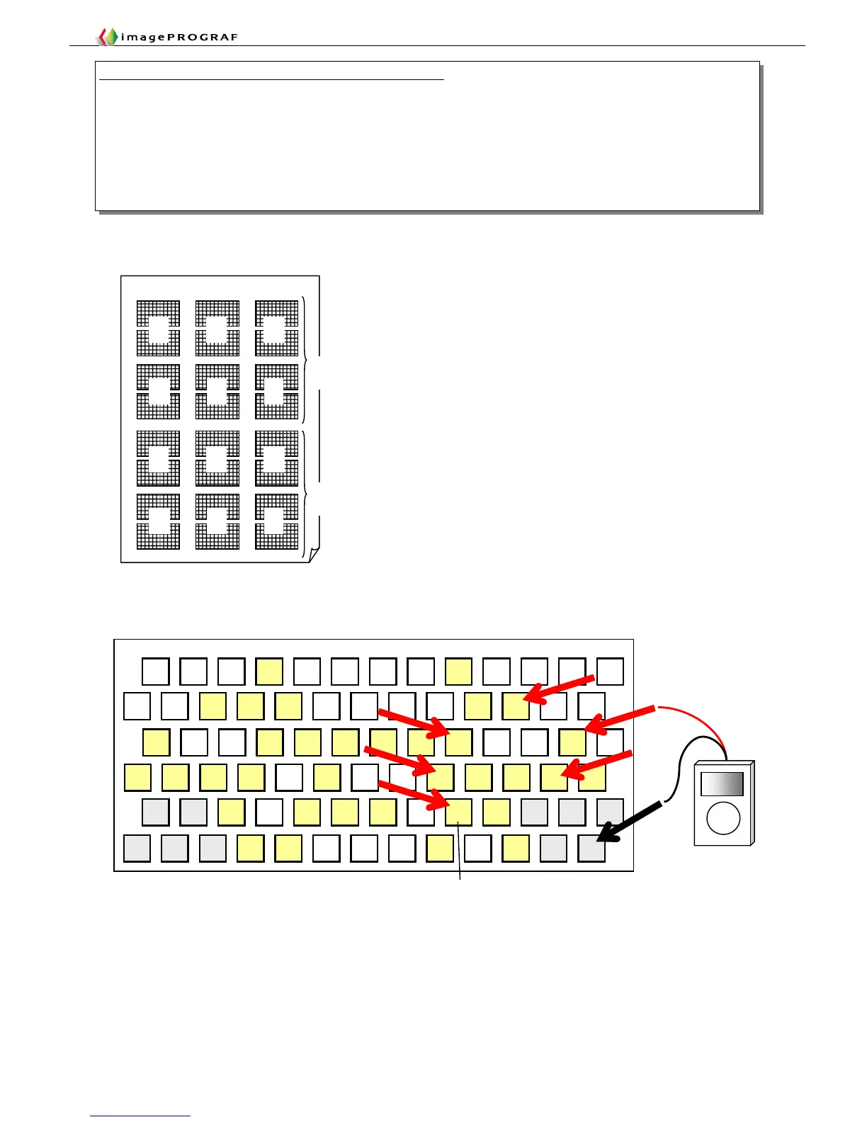
■Nozzle check print and chip layout (Double-head model example)
Layout of head contact pins exposed with the head removed
GND GND GND
B C
D E F
Example 3: Main controller and head contact pin continuity check
1. Identify the color (chip) that has been found to have an imaging failure in a Nozzle Check Print operation.
2. Connect flat cable ③a under test to connector J02 of the flat cable checker.
3. Connect the ― terminal of the tester to any grounding terminal (GND as shown below).
4. Chips (A through F) have a specific color to control each and also have six contacts each. Check all these contacts for
continuity.
5. With the E-chip, for example, apply the + terminal of the tester to the contact at position E shown below to check for
continuity. (An example of making a continuity check on E-chip signals is shown below.)