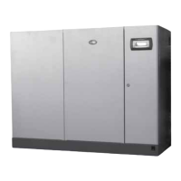
Fig.14.g
Fig.14.h
14.3
Checking
ionisation current
Ionisation current is checked by placing a microammeter set to 10 µA full scale (direct current) in series
with the flame detection electrode. Incorrect positioning of the electrode may lead to a decrease in the
ionisation current and burner shutdown due to incorrect flame detection. In this case, check the correct
position and condition of the electrode, its electrical connections, and the earth connection of the burner.
The ionisation current is normally 5 μA.
Fig.14.i
1 microammeter with 10 µA full scale
2 test equipment
14.4
Flue gas
temperature
sensor
The flue gas temperature sensor is located in the flue and does not require periodical maintenance. If the
sensor needs to be replaced due to a fault, proceed as follows:
l stop the humidifier by turning the switch to 0 (OFF) and checking that the display is off;
l open the electrical compartment to access the panel;
l loosen terminals 10T and 11T (or 10Z and 11Z, see the wiring diagram) on the terminal block in the
bottom of the electrical panel and the probe holder nut on the adapter joint and remove the probe
and the cable.
Then replace the sensor by following the same procedure in reverse.
14.5
Water
temperature
sensor
This does not require periodical maintenance.
To replace the sensor, proceed as follows:
l stop the humidifier by turning the switch to 0 (OFF) and checking that the display is off;
l open the panels to access the water circuit (Fig. 14.a);
l remove the sensor from the stainless steel housing in the level sensor support at the front;
l loosen terminals 12T and 13T (see the wiring diagram) on the terminal block at the bottom and
remove the probe.
 Loading...
