4. Electrical connections
4.1
Wiring
requirements
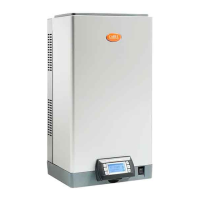
The cables coming from the outside must pass through the side cable glands (see the figure).
Fig.4.a
4.2
Power cable
Before making the electrical connections, disconnect the unit from the mains power supply.
Check that the unit’s power supply voltage corresponds to the rated value shown inside the electrical
panel.
230 V/50 Hz version
Run the power and earth wires into the electrical panel through the tear-resistant cable gland supplied,
and connect the ends to terminal AL (L1, L2, GND), as shown in the figure.
300090_018_R01
GND
L
N
1T 2T 3T 4T 5T 6T 7T 8T 9T 10T 11T 12T 13T 14T
1Z 2Z 3Z 4Z 5Z 6Z 7Z 8Z 9Z 10Z 11Z 12Z
1S 2S 3S 4S 5S 6S 7S 8S 9S 10S 11S 12S 13S 14S
T
1Y 2Y 3Y 4Y 5Y 6Y 7Y 8Y 9Y
Y
6O 7O 8O 9O
O
S
* Z
L1 L2 GND
AL
1U 2U 3U 4U 5U 6U 7U 8U 9U 10U 11U 12U 13U 14U
U
1A 2A 3A 4A
A
AL
Fig.4.b
115 V/60 Hz version
Run the power and earth wires into the electrical panel through the tear-resistant cable gland supplied,
and connect the ends to the terminals on the DIN rail, connected directly to the main transformer
(primary 115 V, secondary 230 V).
30|4. Electrical connections
gaSteam - UG +0300090EN rel. 1.2– 09.10.2018
 Loading...
