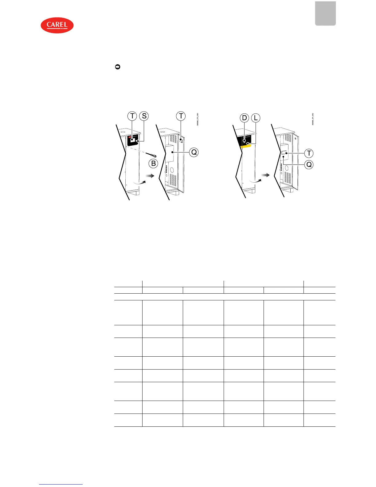
1.5.2 Accessing the electrical panel
Note: the user terminal (T) is located:
l on the indoor model: mounted on the door and accessible from the outside;
l on the outdoor model: inside the unit, in the electrical panel (Q).
Indoor model Outdoor model
Unscrew the screw using a flat-head screwdriver (B) and
open the door to access the electrical panel (Q).
Procedure:
1. Turn the disconnect switch (D) OFF to electrically
disconnect the unit;
2. Turn the key in the lock (L) and open the door to
access the electrical panel (Q).
Fig.1.d
1.6
Material supplied
Once the packaging has been opened and the front panel removed, make sure that all of the components
listed in the table are present.
UG45-90-150 UG180-300 UG450
indoor outdoor indoor outdoor outdoor
Water circuit
Water hose
with
compression
fitting
1 1 1 1 2
Screw-band
hose clamp
4 (UG45-90); 2
(UG150)
4 (UG45-90); 2
(UG150)
4 (UG180); 2 (UG300) 4 (UG180); 2 (UG300) 3
Threaded
hose
coupling
1 1 1 1 2
Spring hose
clamp
2 2 2 2 4
Gas shut-off
valve
1 1 1 1 1
Water shut-
off valve with
gasket
1 1 1 1 2
Probe flanges
with gasket
1 1 2 2 3
Cable gland
PG13.5
1 1 1 1 1
 Loading...


