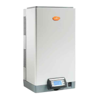
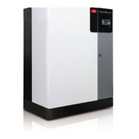
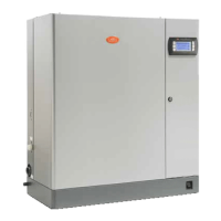
type c.pHC
auxiliary voltage / frequency (V- Hz) 24 / 50-60
maximum auxiliary power (VA) 90
probe inputs (general specifications)
selectable for signals: 0-1 Vdc, 0-10 Vdc, 2-10 Vdc, 0-20 mA, 4-20 mA
input impedance: 60 kΩ with signals: 0-1 Vdc, 0-10 Vdc, 2-10 Vdc
50 Ω with signals: 0-20 mA, 4-20 mA
power supply for active probes (general
specifications)
24 Vdc (24 Vac rectified), Imax= 250 mA
12 Vdc 5%, Imax= 50 mA
alarm relay outputs (general specifications)
250 V2 A (2 A)
type of micro-switching action 1C
remote enabling input (general specifications)
voltage-free contact; max. resistance 50 Ω; Vmax = 24 Vdc; Imax = 5
mA
serial communication three-wire RS485 / Fieldbus / BMS
USBport USBtype A
Ethernet port Ethernet
Tab.16.c
16.1 Heating-water circuit specifications
UOM UG045 UG090 UG150 UG180 UG300 UG450
rated heat output
rated
kW (BTU/h)
33 (112763) 62.5 (213449) 105 (358275) 125 (426518) 210 (716550) 315 (1074825)
minimum 7.8 (26614) 14.7 (50158) 24.7 (84280) 14.7 (50158) 24.7 (84280) 24.7 (84280)
rated heat
input 34.8 (118742) 65 (221789) 108 (368511) 130 (443578) 216 (737023) 324 (1105534)
minimum 8.7 (29686) 16.25 (55447) 27 (92128) 16.25 (55.5) 27 (92128) 27 (92128)
rated steam production
rated
kg/h (lbs/h)
45 (100) 90 (200) 150 (330) 180 (400) 300 (660) 450 (990)
minimum 11.25 (25) 22.5 (50) 37.5 () 22.5 (50) 37.5 () 37.5 ()
max steam temp. °C (°F) 105 (221) 105 (221) 105 (221) 105 (221) 105 (221) 105 (221)
water content in steady operation l 120 120 200 200 415 615
NOx emissions class
5(<70
mg/kW/h
5(<70
mg/kW/h
5(<70
mg/kW/h
4 (<100
mg/kWh)
4 (<100
mg/kWh)
4 (<100
mg/kWh)
CO2
natural
gas (G20)
% vol 9.4 9.4 9.4 9.4 9.4 9.4
natural
gas (G25)
9.3 9.3 9.3 9.3 9.3 9.3
propane
(G31)
11.2 11.2 11.2 11.2 11.2 11.2
butane
(G30)
11.6 11.6 11.6 12 12 12
CO mg/kWh * <25 * <60 * <60 * <60 * <60 * <60
D. flue gas pipe***
mm
80 (3”) 80 (3”) 80 (3”) 2xØ80 (3”) 2xØ80 (3”) 3xØ80 (3”)
D. air intake pipe*** 80 (3”) 80 (3”) 80 (3”) 2xØ80 (3”) 2xØ80 (3”) 3xØ80 (3”)
D. steam hose 2x Ø40 2x Ø40 1x Ø80 4x Ø40 2x Ø80 3x Ø80
natural gas combustion flow-rate (G20) rated
m
3
St/h**
3.68 6.87 11.45 13.4 22.7 34.4
minimum 0.9 1.75 2.91 1.67 2.85 2.85
natural gas combustion flow-rate (G25) rated 4.2 8.7 14.6 17.5 29.2 43.8
minimum 1.02 1.98 3.3 1.98 3.3 3.3
propane combustion flow-rate (G31) rated 1.43 2.68 4.47 5.36 8.94 13.41
minimum 0.48 0.68 1.13 0.68 1.13 1.13
butane combustion flow-rate (G30) rated 1.1 2.06 3.43 4.12 6.86 10.29
minimum 0.37 0.545 0.91 0.545 0.91 0.91
gas supply pressure
natural
gas (G20)
Pa/mbar/PSI
2000/20/0.9 2000/20/0.9 2000/20/0.9 2000/20/0.9 2000/20/0.9 2000/20/0.9
natural
gas (G25)
2000/20/0.9 2000/20/0.9 2000/20/0.9 2000/20/0.9 2000/20/0.9 2000/20/0.9
propane
(G31)
3000/30/0.44 3000/30/0.44 3000/30/0.44 3000/30/0.44 3000/30/0.44 3000/30/0.44
butane
(G30)
3000/30/0.44 3000/30/0.44 3000/30/0.44 3000/30/0.44 3000/30/0.44 3000/30/0.44
max allowable pressure drop for Pa/mbar/PSI 90/0.90/0,013 82/0.82/0,012 82/0.82/0,012 95/0.95/0,014 95/0.95/0,014 95/0.95/0,014
114|16. General features and models
gaSteam - UG +0300090EN rel. 1.2– 09.10.2018
 Loading...
