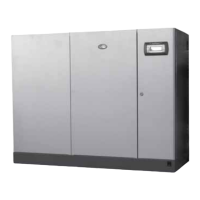
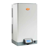
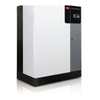
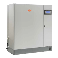
Fig.8.e
Systems set up in this way will be able to cover the humidification requirement. In this specific case, the
Master will always be the unit with the lowest IP address of those connected to the signal/probes. If
necessary, an additional humidifier (backup) can be installed to cover request in the event of malfunctions
on one of the units in the system.
8.4
System
configuration
To configure the Master/Slave system, proceed as follows:
1. Connect the probes or the external signal to the unit and complete the configuration (control type,
type of signal, maximum production …);
2. Set the IP addresses of the individual units so that they belong to the same subnetwork (subnet mask);
the screen index for this configuration is Eh02 (E. Settings – h. Supervision). The IP address is set on the
display on each unit, assigning a different address to each unit in the same subnetwork. If necessary,
contact the local network administrator. Remember that the default address for each unit is
192.168.0.1, and the default subnet mask is 255.255.255.0.
3. Connect the units making up the Master/Slave system to the local Ethernet network via a switch. If
using just two units, an RJ45 category 5 cable can be used, connected directly to the Ethernet ports on
the two c.pHC controllers.
4. Configure the Master/Slave system by enabling the units one at a time (this operation can be
performed on the display on any of the units):
I. Display screen index Ed01 and then access configuration mode by pressing “PRG”;
II. Enter the IP address for “Unit 1” and confirm by pressing “Enter”;
III. Repeat the operations described above (1 and 2) for all the other units in the Master/Slave system.
(The units will join the Master/Slave system (online status) immediately after being connected to
the network.)
Note:
l the Master unit will always (automatically) be the one with the lowest IP address out of the units
connected to the probes or external signal;
l it may take a few seconds (max 10 s) for the Master to start sending the production request to the
Slave/Slaves. This is also true when, automatically, the Master unit is changed (for example, in the
event of malfunctions).
A cascaded connection of several units can also be made by simply using terminals 11U and 12U, which
provide the production request (0-10 V).
8.4.1 Maximum production
In the same way as for the individual unit configuration, for the Master/Slave system the maximum
capacity can also be set.
86|8. Master/Slave system
gaSteam - UG +0300090EN rel. 1.2– 09.10.2018
 Loading...
