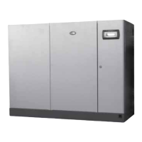
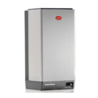
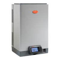
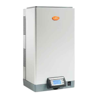
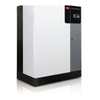
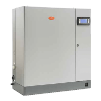
Fig.5.a
5.2.3 Type of calibration
Two different types of burner calibration are available:
A. Guided;
B. Manual.
The guided procedure automatically provides the user, step by step, with all the information necessary to
complete the calibration process. For the manual procedure, follow the instructions below.
5.2.4 Burner calibration at maximum output
Force the burner to operate at maximum output, as shown in the table, by setting the fan to the
maximum speed and verifying by flue gas analysis that the CO2 value corresponds to the table.
If the values measured are different, proceed as follows:
1. open the front door;
2. adjust the gas flow regulator B (figure) using a flat- head screwdriver or a 4 mm spanner: turn
anticlockwise to increase the CO2 value, clockwise to decrease it;
3. wait until the CO2 value stabilises, then check again and, if necessary, repeat the operations.
Fig.5.b
CO2 (%)
Gas min max
G20-G25 8.5 ±0.3 9.4 ±0.2
G30-G31 9.9 ±0.3 10.5 ±0.3
Tab.5.b
5.2.5 Burner calibration at minimum output
Force the burner to operate at minimum output, by setting the fan to the minimum speed as described
previously and verifying by flue gas analysis that the CO2 value corresponds to the table.
48|5. Preparing for operation
gaSteam - UG +0300090EN rel. 1.2– 09.10.2018
 Loading...
