EasyManua.ls Logo

CARRARO COMPACT Vigneto - Page 152

CARRARO COMPACT Vigneto
296 pages
Print Icon
To Next Page IconTo Next Page
To Previous Page IconTo Previous Page
Loading...


5

revision 0 date: 07/19 doc. AG525990
      
  

 

 
 
           
     

        

 
 
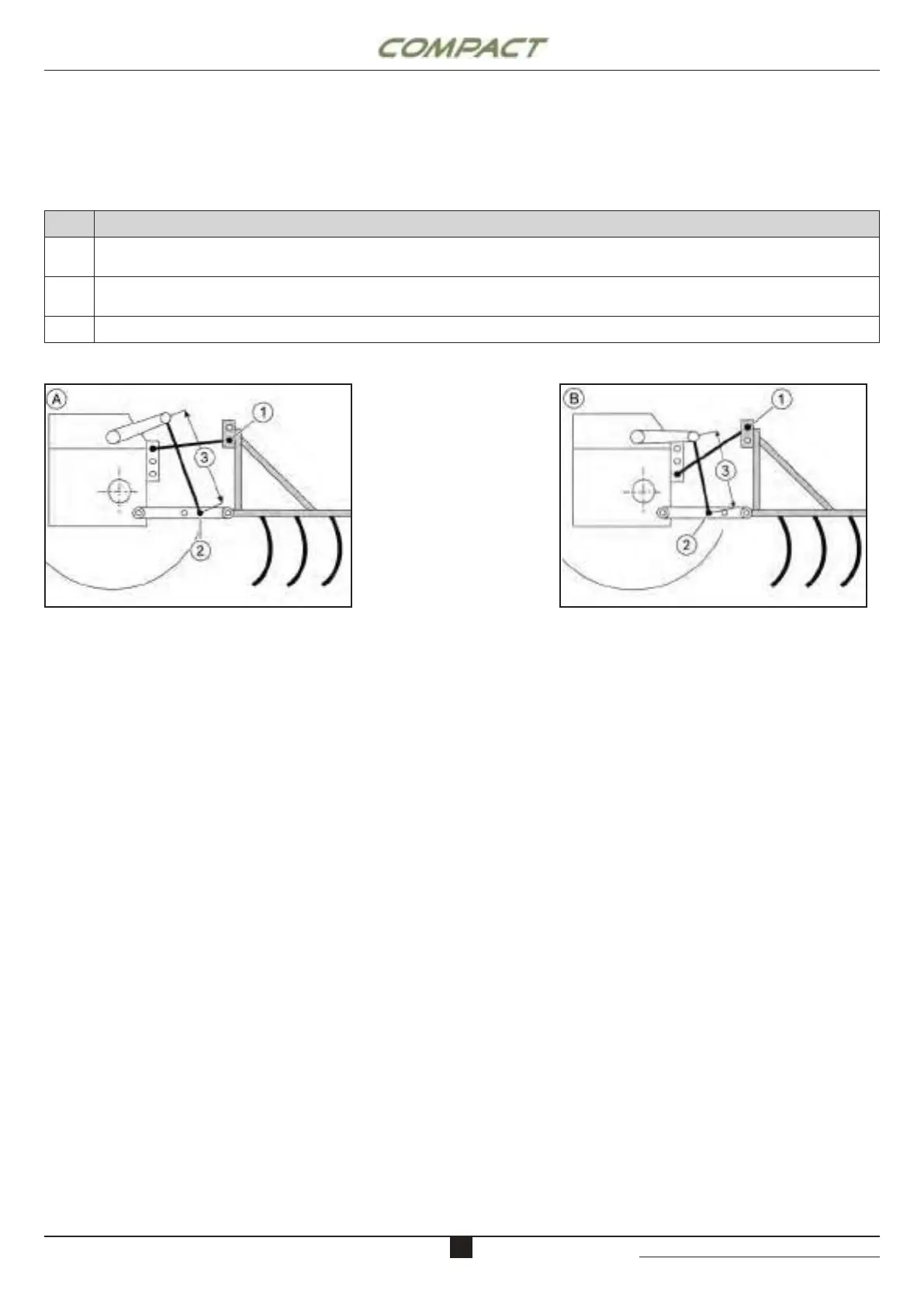
- To achieve maximum lifting capacity (heavy
implement), use the conguration corresponding to
maximum mechanical benet (A):
- Top link in the upper hole on the tractor side, in the
lower hole on the implement side (1).
- Adjustable links xed in the hole farthest back.
- Adjustable links fully extended (3).
- If the load to be lifted is light, the following hitching
conguration corresponds to the minimum
mechanical benet (B):
- Top link in the lower hole on the tractor side, in the
upper hole on the implement side (1).
- Adjustable links xed in the hole farthest forward.
- Adjustable links fully shortened (3).
       

       

The 3-point hitch enables a wide range of implements
to be hitched. You must identify the most appropriate
hitch geometry for each application. To achieve this, the
following components can be adjusted:
DESCRIZIONE / Description
1


Top link (attachment point for the top link in relation to the wheel axis and the link length).

Lower connecting rods (attachment point between the adjustable links on the lower bars).
Adjustable links (adjustable link length).

Table of Contents

Related product manuals