CHAPTER 7 - ELECTRICAL
7-4
Issued 8-04 Bur 6-34551NA
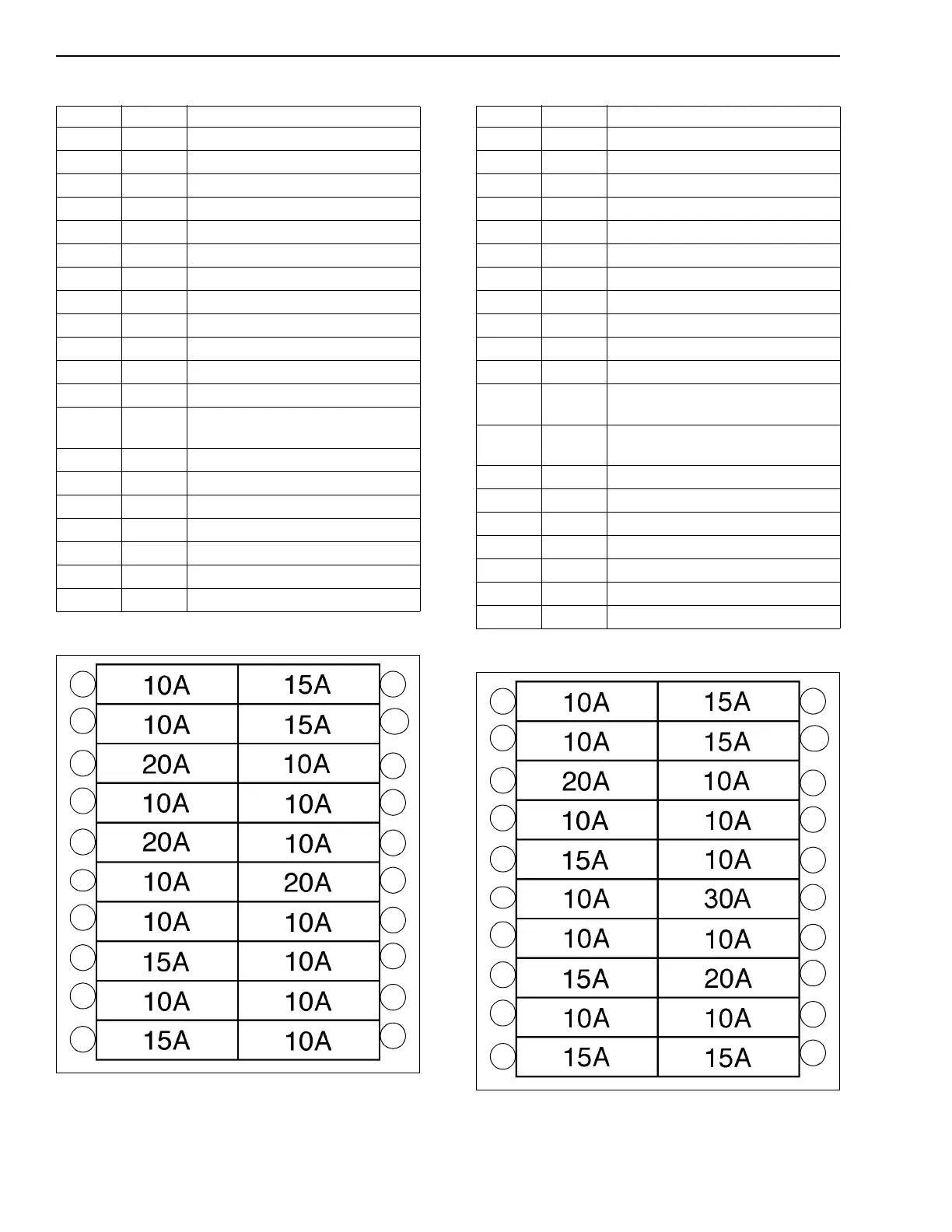
FUNCTION OF THE FUSES - CX75SR, CX80
FUSE LOCATION - CX75SR, CX80
CT02D248
Figure 3
FUNCTION OF THE FUSES - CX135SR
FUSE LOCATION - CX135SR
CT02E010
Figure 4
FUSE AMP FUNCTION
110
Memory
210
Key switch
320
Air conditioning, heater
410
Overload indicator controller
520
Working lights
610
Swing brake relay
710
Not used
815
Windshield wiper/washer
910
Horn
10 15
2 flow breaker/grab option
11 15
Accelerator motor
12 15
Cigarette lighter
13 10
Air-conditioning (optional) and
instrument panel lighting
14 10
Rotary light relay
15 10
Hydraulic control cancellation
16 20
Optional power connector
17 10
Travel mode relay
18 10
Fuel filling pump (optional
19 10
Optional power connector
20 10
Optional power connector
11
12
13
14
15
16
17
18
19
20
1
2
3
4
5
6
7
8
9
10
FUSE AMP FUNCTION
110
Memory
210
Key switch
320
Air conditioning, heater
410
Overload indicator controller
520
Working lights
610
Swing brake relay
710
Not used
815
Windshield wiper/washer
910
Horn
10 15
2 flow breaker/grab option
11 15
Engine electronic box
12 15
Operator’s seat compressor
(optional)
13 10
Air-conditioning (optional) and
instrument panel lighting
14 10
Rotary light relay
15 10
Hydraulic control cancellation
16 30
Glow plugs
17 10
Travel mode relay
18 10
Fuel filling pump (optional
19 10
DC-DC (24 V - 12 V) converter
20 15
Engine emergency shut down
11
12
13
14
15
16
17
18
19
20
1
2
3
4
5
6
7
8
9
10