CHAPTER 3 - INSTRUMENTS AND CONTROLS
3-10
Issued 8-04 Bur 6-34551NA
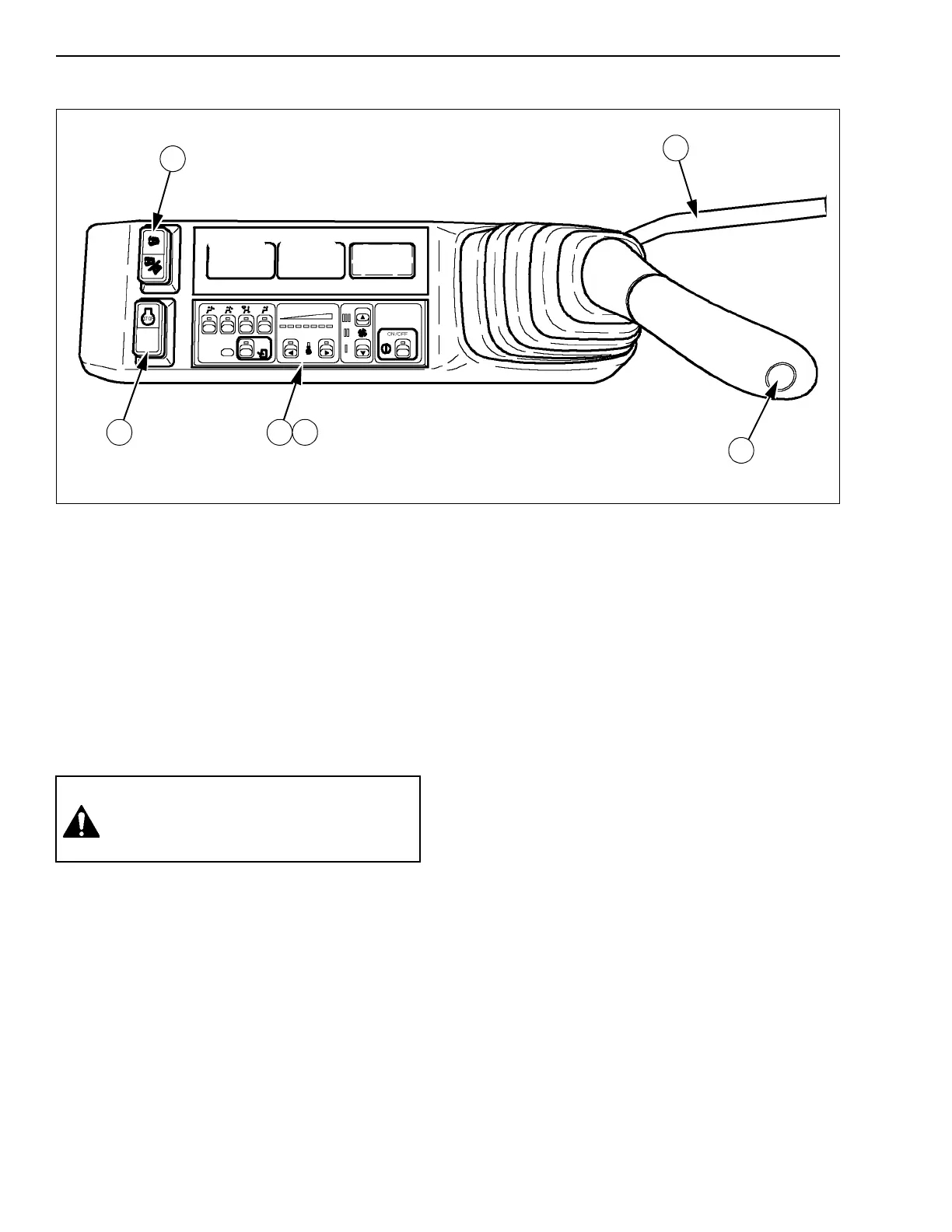
LEFT-HAND CONTROL ARM FOR CX135SR
CT02C047
Figure 18
1. HORN
To sound the horn, press at the end of the
left-hand control lever.
IMPORTANT: Always sound the horn before
operating the machine.
2. FUNCTION CANCELLATION LEVER
The shape of the function cancellation lever was
designed to prevent the operator from leaving the
operator’s compartment without having raised
the lever beforehand. See function cancellation
lever.
3. OPTION CONTROL (Optional)
This two-position switch enables the activation of
options such as the hydraulic breaker, grab,
shears, etc. Place the switch in one of the two
positions depending on the accessories to be
used. See Auxiliary hydraulic systems in the
Operating Instructions section.
4. EMERGENCY SHUT DOWN SWITCH
This switch shuts down of the engine in case of
an emergency. See Shutting down the engine in
the Operating Instructions section.
IMPORTANT: This switch should only be used in
case of an emergency. Do not use it on a
day-to-day basis.
5. HEATING AND VENTILATION CONTROL
See Heating and ventilation control for its use.
6. HEATING, VENTILATION OR
AIR-CONDITIONING CONTROL (Optional)
See Heating, ventilation or air-conditioning
control for its use.
2
1
3
4 5 6
WARNING: To access or exit the operator’s
compartment, the function cancellation lever
must be in the raised position. Never try to
avoid this basic requirement.