PC Connection
Chore-Tronics® 3 Control PC Connection
MT2398C
113
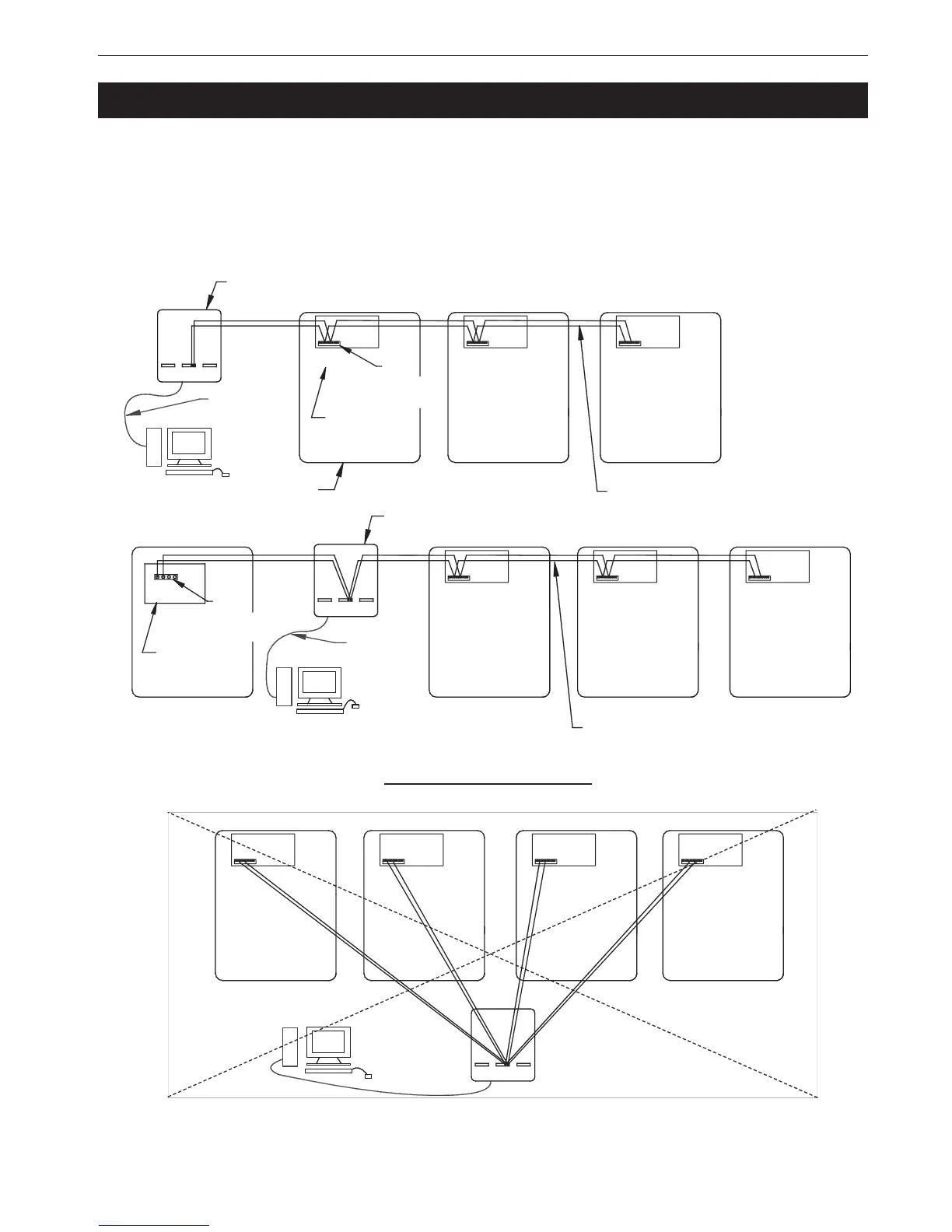
The Controls in each house are connected together at the FNET Terminal Connectors
as shown below. To see where the FNET Terminal Connectors are located on the I/
O Board see Figure 48. Use only Twisted Pair Wire (Chore-Time Part No. 42208).
The Interface Box can be wired in anywhere either at the beginning of your string, at
the end, or between Controls; but not to more than one Control as shown in Figure
43 below.
FNET
Connection
Typical
I/O Board
Typical
PC
Chore-Tronics Control
Interface
Box
FNET
Connection
Typical
I/O Board
Typical
Interface
Box
Twisted Pair Wire Typical
PC
1842-136 12/04
or Modem
or Modem
PC
or Modem
9 Pin Serial
Cord to PC
9 Pin Serial
Cord to PC
Incorrect Installation
Twisted Pair Wire Typical
Figure 43. PC Connection