Chore-Tronics® 3 Control Control Installation
MT2398C
111
When testing the Toggle Switches for the Curtain and Inlet Machines, be sure to test them one
Switch at a time.
After testing the open switch, place it in the manual "off" position before placing
the close switch in the
manual "on" position. If you try to put both switches in the manual "on" at the same time you will send a
double signal to the Curtain Machine Motor.
Testing the Back Up Box
To test the Back Up Box, first turn the power off to the Chore-Tronics
®
3 Control only. This should cause
the Tunnel Curtain to open and the first set of Back Up Fans should activate. If this test is successful, turn
the power back on to the Chore-Tronics
®
3 Control. Then adjust thermostat number one until it activates.
Then adjust the second thermostat until it activates. This should cause the second set of Back Up Fans to
activate. After all Back Up Fans are operating, deactivate the first two thermostats. Than adjust the third
thermostat until it activates. This should cause the Back Up Heaters to activate.
After all of the outputs and back ups have been successfully
tested, make sure all manual toggle switches
are in the manual "off" position and proceed to the "Setup" portion of this manual beginning on Page 18.
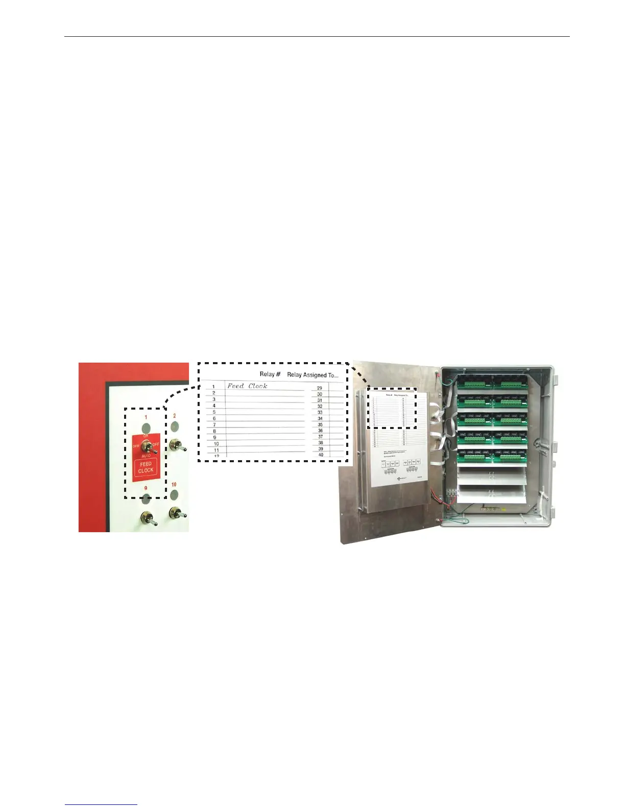
Wiring of Outputs
The outputs for the Chore-Tronics Controls (Fans, Curtain Machines, Brooders, etc.) are wired to one of
the Relays on the Relay Module or (RM Board(s). The RM Board consists of eight 1hp motor load Relays.
Each Relay has single-pole, single-throw normally open contacts. It is strongly recommended that the
assignment of outputs to the Relays be done before starting to wire the Control. This will make routing of
the electrical wires through the Relay box much easier (See Figure 40).
Figure 40. Relay Assignments
The appropriate output stickers should be placed over the toggle switches used, if it has not already been
done prior to mounting. Please see the wiring diagrams on the following pages for wiring Chore-Time
ventilation equipment. (Wiring diagrams for Fans, Linear Lifts, Super Lifts, Brooders, Turbo Cool, Mister
Cool). For other types of equipment please refer to wiring diagrams supplied with the equipment.