Control Installation Chore-Tronics® 3 Control
104
MT2398C
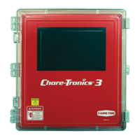
PDS Flush Feedback Wiring
If a PDS Drinker Control is being used to automatically flush water lines, then the Control can ignore
pulses coming from the Water Meter(s) while flushing is taking place. If this option is used then a dry
contact relay must be connected to one of the Digital (DI) Inputs of the IO Board. The coil of the relay
should be energized whenever the Control begins its flushing sequence. See Figure 33 below for
connecting the relay to the IO board of the Control.
2
(DI) of your Choice
Item Description
1 PDS Flush Feedback Control
2 I/O Board Digital Input (DI)
terminal of your Choice
Figure 33. PDS Flush Feedback Wiring
1
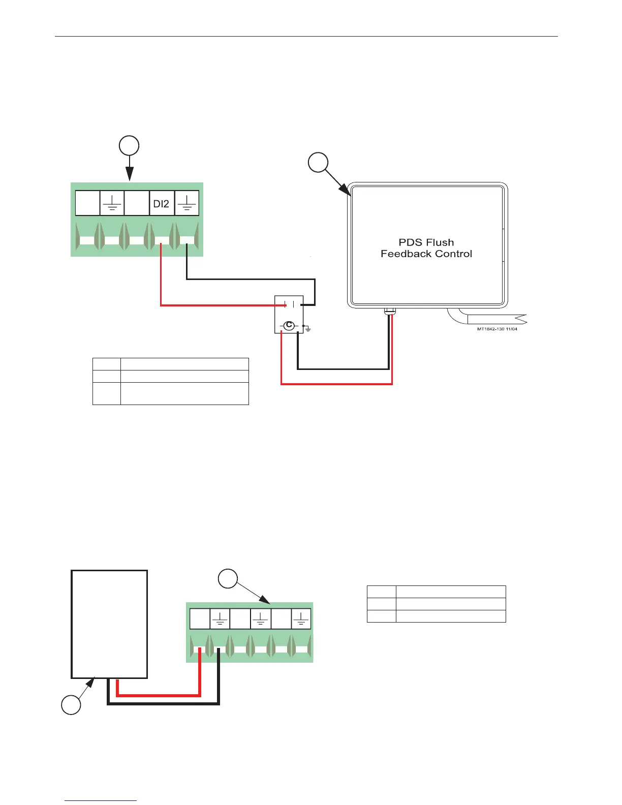
Remote Light Dimmer Control Wiring
Before connecting the I/O board to a Light Dimmer, be sure to check that the light dimmer is equipped
for remote control dimming. The Light Dimmer must be able to accept a 0-10 or 10-0 Vdc signal from the
I/O board. Refer to the information provided by the Light Dimmer manufacturer for remote dimming
wiring instructions.
The Light Dimmer connects to the I/O board
at the Analog Output #1 (AO1) (See Figure 34 below). Be
sure that the positive terminal on the I/O board matches with the positive wire/terminal on the Light
Dimmer.5
Light Dimmer
0-10 Vdc Input
Figure 34. Remote Light Dimmer Control Wiring
Item Description
1 Light Dimmer
2 Analog Output #1
1
+
-
+
-
2