Control Setup Chore-Tronics® 3 Control
29
MT2398C
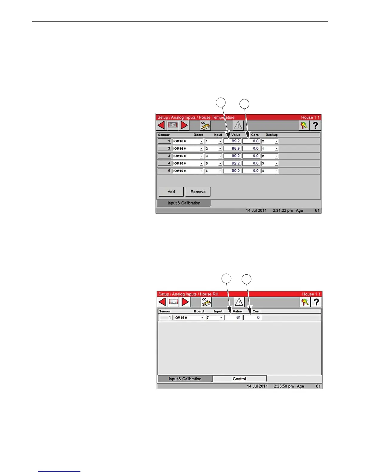
Analog Input Calibration
The re-calibration section of this screen should not need to be used at initial installation and start-up of
the Control unless natural ventilation is used. If natural ventilation is being used, then the Potentiometers
will need to be calibrated at this time. If it is felt that one of the Inputs needs to be re-calibrated perform
the following steps…
Temperature Sensor Calibration
1. To re-calibrate the Temperature Sensors, first obtain a digital thermometer that has a readout of at
least + - 1°. Do not use a temperature gun. A temperature gun measures an object’s temperature, not
air temperatures.
2. Place the digital thermometer next to
the Temperature Sensor that is being
re-calibrated. Take the reading from
the digital thermometer and enter that
number under the Value column of the
Sensor being calibrated.
3. The Correction column is used only
for service information and to return
the Control to the factory settings. The
settings should be reset to factory
whenever a re-calibrated Temperature
Sensor is replaced. To return to factory
settings change the number under the correction column by one digit. This will cause the correction to
automatically zero out and return to factory setting.
All Temperature Sensors are calibrated the same way. (Outside, Spare and Aux temperature sensors)
2
3
Relative Humidity Sensor Calibration
1. To re calibrate the Relative Humid-
ity Sensor first obtain a sling psy-
chrometer or another humidity
measuring device.
2. Operate the psychrometer in the
same area that the Relative Humidity
Sensor is installed. Take the reading
on the psychrometer and compare it to
the reading on the Setup/Analog In-
puts/ House RH Screen. If the read-
ings do not match, then change the
reading under the Value column to
match the reading of the psychrome-
ter.
3. The correction column is to be used for service information and for returning to factory settings
only.
2
3