Control Installation Chore-Tronics® 3 Control
94
MT2398C
Wiring the Control
Note As with all electronic controls, we recommend the use of a backup system. This
will provide continuous operation in the unlikely event of Control failure. Use
the current Back Up Box Manual for wiring instructions.
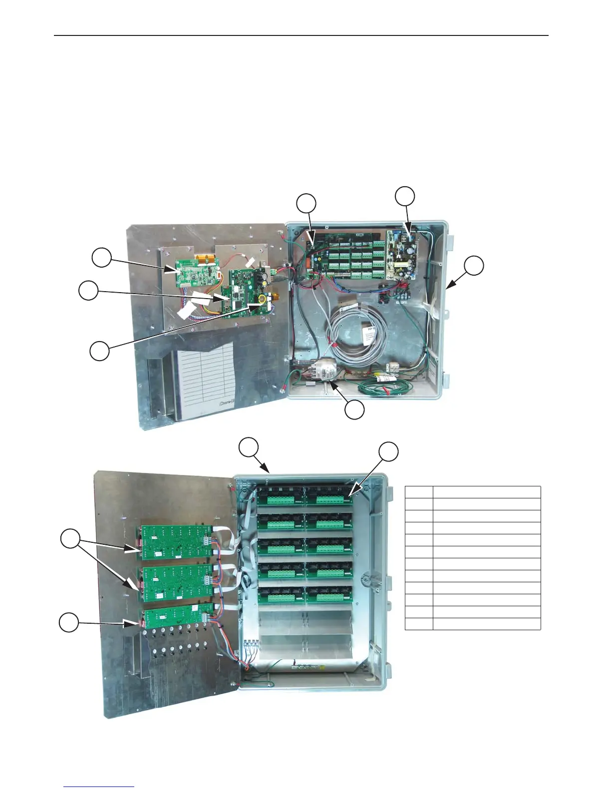
The Chore-Tronics
®
3 Controls consist of several different types of boards shown in
Figure 16. The two Boards involved in wiring the Controls are the I/O Board and the
Relay Module (RM Board).
Item Description
1 Main Box
2 Relay Box
3I/O Board
4 Power Supply
5 RM Board (Relay Module)
6 SP (Static Pressure) Sensor
7 Display Board
8 KD Board
9 HI Basic Board
10 IMCM.16 Board
11 IMCM.8 Board
3
1
4
5
6
7
8
10
11
9
2
Figure 16. Wiring/