Control Installation Chore-Tronics® 3 Control
96
MT2398C
Analog Inputs
Analog Inputs consist of temperature sensors, the static pressure sensor, the relative humidity sensor and
potentiometers (natural ventilation only). These inputs can be wired to any of the analog inputs (AI 1 thru
AI 12) on the I/O board. The inputs that are pre-assigned are temperature sensors 1, 2 and 3, and the static
pressure sensor. Use the diagram located on page 137 to record where each Input is wired to the Control.
Temperature Sensors
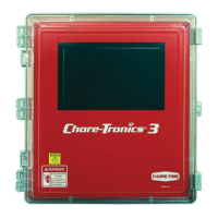
The Temperature Sensors require Non-Shielded 20 Gauge Twisted Pair Wire. This wire is available through
Chore-Time. When routing this wire in the house be sure to keep it a minimum of 12"(305mm) away from
line voltage wiring. If there is a need for the Sensor wire to cross line voltage wires cross them at a 90° angle
to each other as shown below.
Figure 19. 90° Cross-over
Item Description
1 Non-Shielded Twisted Pair Wire
2 Line Voltage Wiring
90°
1
2
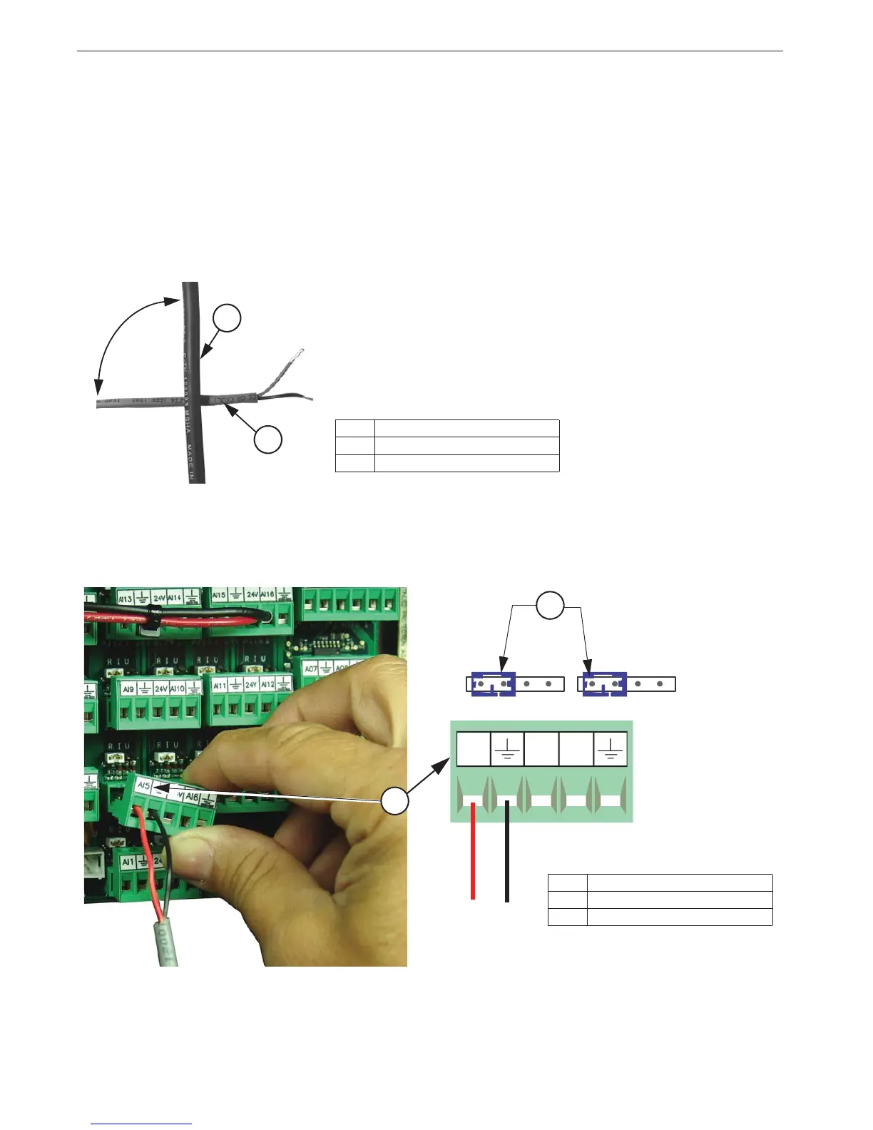
The Temperature Sensor wires can be connected to any one of the Analog Inputs (AI1 through AI16) of
the I/O board. Whatever AI Inputs the Temperature Sensors are connected to, make sure that the blue
jumper above each Input is set to "R" as shown in Figure 82 below. There are no polarity restrictions for
the Temperature Sensors.
Item Description
1 Analog Input (AI5)
2 blue jumper set to "R"
Figure 20. Temperature Sensor Wiring
Black
Red
1
2