Control Installation Chore-Tronics® 3 Control
97
MT2398C
Temperature Sensors Continued.....
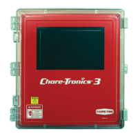
Route the wire through the back of the Temperature Sensor and connect it as shown in Figure below. Pull the
wire through the back of the box until a drip loop is formed as shown.
Mv1701-010 10/01
3
1
Front View
(with Lid Off)
2
Figure 21. Drip Loop
Item Description
1 Temperature Sensor (Back Side)
2 Non-Shielded Twisted Pair
3 Drip Loop
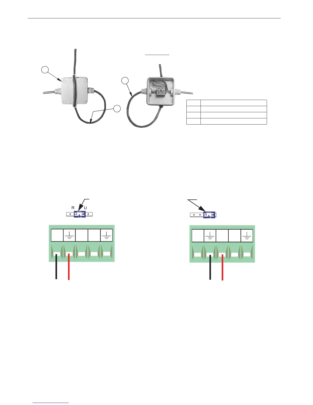
Static Pressure (SP) Wiring
There is a Static Pressure Sensor included with every Chore-Tronics
®
3 Control. This sensor is pre-wired
from the factory to Analog Input #4 (AI 4) (Figure 22). If it is desired, the Static Pressure Sensor can be
wired to any of the Analog Inputs (AI1 through AI16) (See Figure 23 for example wired to AI1). Please
note that the Red wire must always be connected to the +24 volt terminal, the Blue wire must be connected
to the AI terminal being used and the Black wire must be connected to the ground terminal of the analog
Input being use. Make sure that whichever AI Input the SP sensor is connected to, that the blue jumper
above the Input is set to "U" position as shown.
Figure 23. Static Pressure Sensor
Wired to AI1
Blue Jumper in the "U" position
Blue Jumper in the "U" position
Figure 22. Static Pressure Sensor
Pre-wired to AI15
Black
Red
Red
Black