Chore-Tronics® 2 Control Control Installation
MT1843B
77
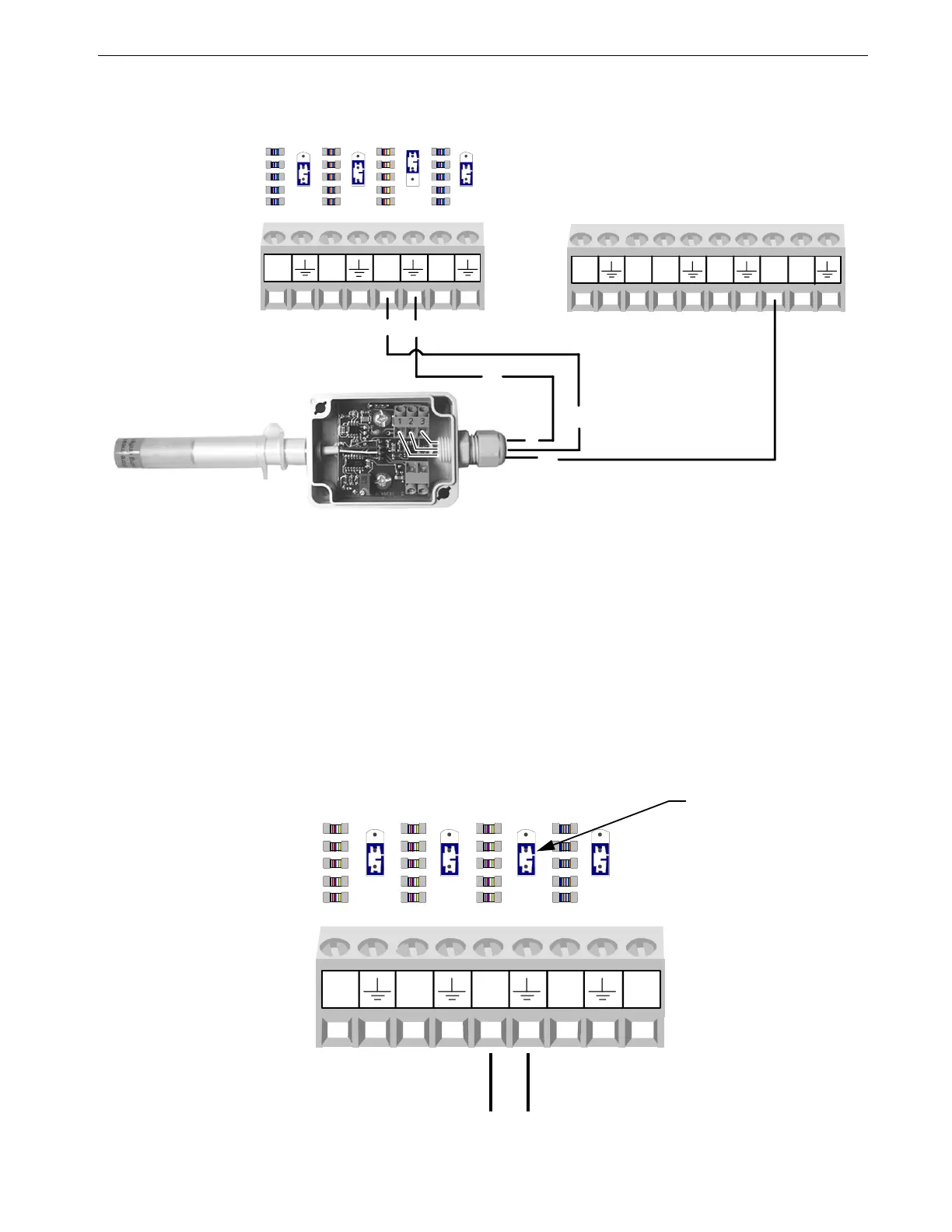
Alternative Relative Humidity Sensor(RH) Wiring
The Relative Humidity can also be wired to 12V. (See Figure 88).
Potentiometer Wiring (Natural Ventilation only)
If natural ventilation is being used, the Potentiometer(s) that are attached to either the
main curtain machine(s) (Internal Potentiometer), or the main curtain cables
(External Potentiometer) need to be wired to the Chore-Tronics
®
2 I/O Board. The
Potentiometers need to be connected using the same Twisted Pair Wire that is used
for the Temperature Sensors and follows the same wiring rules. Each Potentiometer
needs to be wired to one of the Analog Input (AI) Terminals on the IO board. Make
sure that whichever AI Input the Potentiometer is connected to that the Blue Jumper
above the Input is set to "R" (See Figure 89). To connect the sensor wire to the
Potentiometer itself, please see Chore-Time instruction manual MV1251 for internal
Potentiometer wiring, or MV1566 for external Potentiometer wiring.
MT1843-004 4/05
U
R
U
R
U
R
AI5
AI6
AI7
AI8
1
3
2
3
3
2
U
R
DI1
12V
DI2
DI3
DI412V
Figure 88. Relative Humidity Sensor Wiring
To Potentiometer
Blue Jumper set to
the "R" position
MT1842-095 11/04
U
R
U
R
U
R
U
R
AI9
AI10
AI11 AI12
24V
Figure 89. Potentiometer Wiring