Control Installation Chore-Tronics® 2 Control
78
MT1843B
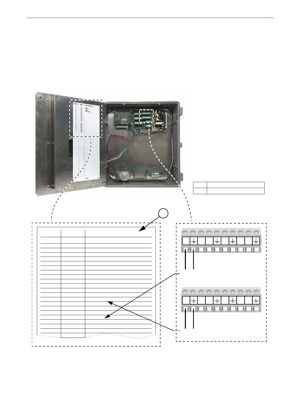
Digital Inputs Wiring
Digital inputs consist of Water Meters, Feed Scales, Air Speed Sensor, Low Water
Pressure Switch, Max Feed Run Time Alarm Input, and PDS Flush Feedback. These
Inputs can be wired to any of the digital inputs (DI 1 thru DI 8) on the IO board
(Figure 90 below). Complete the analog input Assignment diagram on page 113 to
indicate where each digital input is connected to the IO board and also record it on
the Input Assignment Decal (Item 1, Figure 90) that is placed on the Cover Plate
inside the Chore-Tronics
®
2 Main Box. Also refer to the following sections for
information specific to each type of digital input.
Input Assigned To...
Sensor 1
Sensor 2
Sensor 3
Static Pressure
Input #Board #
AI 10
0AI 2
0AI 3
0AI 4
0AI 5
0AI 6
0AI 7
0AI 8
0AI 9
0AI 10
0AI 11
0AI 12
DI 1
0
0
0
0
0
0
0
0
DI 2
DI 3
DI 4
DI 5
DI 6
DI 7
DI 8
MT1842-096 11/04
Water Meter
Feed Scale
MT1842-096b 11/04
DI1
12V
DI2
DI3
DI412V
DI5
12V
DI6
DI7
DI812V
To Feed Scale
To Water Meter
Figure 90. Digital Input Wiring
1
Item Description
1 Input Assignment Decal