Chore-Tronics® 2 Control Control Installation
MT1843B
81
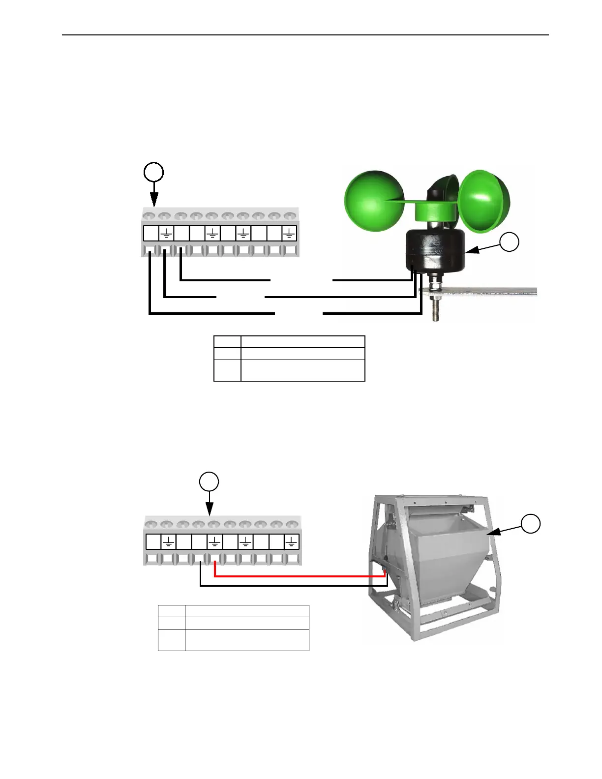
Airspeed Sensor Wiring
The Airspeed Sensor requires a three conductor wire to connect the Sensor to one of
the Digital (DI) Inputs on the IO board. It is recommended that the digital input
chosen is adjacent to one of the 12 volt outputs on the IO board (Figure 94). The
Brown wire on the Sensor needs to be connected to the +12 volt output, the Green
wire on the Sensor needs to be connected to the ground terminal of the digital input
being used, and the White wire needs to be connected to the DI(x) terminal of the
digital input being used.
Feed Scale Wiring
If one or more Feed Scales are used, they need to be connected to one of the Digital
(DI) Inputs on the IO board using Twisted Pair Wire. Connect the switch located on
the side of the Feed Scale to the IO Board using the blue and brown wires (Figure
95). See manual MT1811 for more information.
1842-127 12/04
DI1
12V
DI2
DI3
DI412V
2
(DI) of your Choice
Item Description
1 Airspeed Sensor
2 I/O Board Digital Input (DI)
terminal of your Choice
Figure 94. Airspeed Sensor Wiring
BROWN
GREEN
WHITE
1
1842-127 12/04
DI1
12V
DI2
DI3
DI412V
Item Description
1 Feed Scale
2 I/O Board Digital Input (DI)
terminal of your Choice
Figure 95. Feed Scale Wiring
2
(DI) of your Choice
1