Operation Overview
● LVP
The design of LVP is mainly to prevent the UUT from sudden voltage drop to 0V and rise
again when the Von point is set to 0V or in current loading state at “LOAD ON” as it could
cause the voltage or current to overshoot. Also it could damage the UUT or Electronic Load
if the UUT is connected.
The LVP is a default protection voltage set internally. When the Electronic Load is under this
voltage and in loading mode, it does not perform current loading until the external voltage is
larger than the LVP set protection voltage. Therefore, there will be no overshoot even though
the Von point is set to 0V or the voltage is suddenly dropped to 0V and raised again. This
way is to prevent the overshoot to damage the UUT and Electronic Load.
When high voltage models are in used, the “CC,CP V RANGE SELECT”
is set to “HIGH” and “LVP” is set to protection, it may not able to operate
the maximum current under minimum working voltage as the LVP
default protection voltage range is about 0.02V~1.2V.
For example,
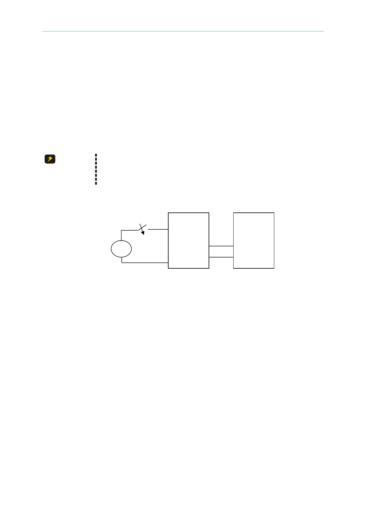
Figure 3-23 Power, UUT & Electronic Load Connecting Diagram
(1) When the Von Point is set to 0V and the LVP sets no protection during “LOAD ON”,
current overshoot will occur on the Electronic Load when the Switch (SW) is off. It may
damage the UUT and Electronic Load under this circumstance as shown in Figure 3-24.
UUT
Electronic
Load
 Loading...

