Programmable DC Electronic Load 63600 Series Operation & Programming Manual
only
exists in dual
This key is used to select the left channel or right channel
directly for the dual channel module.
This key is used to select the system operation mode for EDIT
or changed the next parameter when press EDIT key again.
This system provides HIGH, MIDDLE or LOW loading range for
data input. The low range offers a better accuracy than that of
high range. Whenever this key is pressed, the range will be
The system provides other functions of TIMING, SINE WAVE
DYNA, OCP TEST, AUTO_SEQUENCES for battery discharge,
fuel cell and power supply testing. (Press ADVA repeatedly will
switch the function in the sequence of TIMING SINE WAVE
DYNA OCP TEST AUTO SEQUENCES accordingly for
users to edit and test. This key can define the default mode for
power on. Press and hold this key for 3 seconds to save is the
This key is used to trigger the short circuit function. (Active at
load ON status)
This key is used to start or stop sinking current from the power
supply.
This key is used for confirming data entry.
To select the other measurement and editing parameters.
To enter into the setup of system configuration.
or
These 2 keys are used to change the cursor position of data
when operating using rotary knob. Or, under configuration setup,
use them to select the desired parameter.
Under configuration setup, this knob is used for changing
options of a parameter. On data entry, it changes values of the
cursor position which is moved by the above 2 arrows.
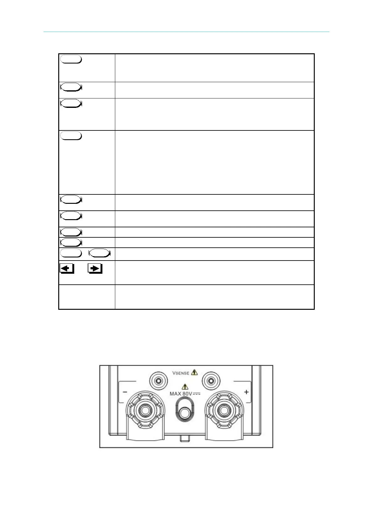
Front Panel Connectors
There are two Vsense connectors and two Load connectors in the single channel
module panel, but there are four Vsense connectors and four Load connectors in the
dual channel module panel. Figure 4-7 shows the front panel Connectors of the Module.
A. Single Channel Module
 Loading...