DIAGNOSIS AND TESTING - PEDAL POSITION
SENSOR
Refer to Appropriate Diagnostic Information.
REMOVAL
(1) Remove battery ground cable terminal from
battery negative post and isolate.
(2) Under instrument panel, remove silencer panel
below lower steering column cover.
(3) Press release tab to the left (Fig. 11), then
remove bulkhead connector from bracket by pulling it
toward lower steering column cover.
(4) Move bulkhead connector toward left side of
vehicle as far as its wires will allow. Do not over-
stress wiring.
(5) Remove two mounting screws securing pedal
position sensor in place (Fig. 12).
(6) Remove pedal position sensor from bracket.
(7) Disconnect wiring connector and remove pedal
position sensor.
INSTALLATION
(1) Connect wiring connector to pedal position sen-
sor.
NOTE: Make sure pin in pedal assembly fits into
slot in sensor carriage when installing sensor.
(2) Place sensor against mounting bracket and into
brake pedal (Fig. 12). Move carriage as necessary to
align slot with pin. Install two mounting screws.
Tighten screws to 7.5 N·m (66 in. lbs.) torque.
(3) Align the bulkhead connector mounting slot
with its bracket and install it, locking it in place.
(4) Install silencer panel below lower steering col-
umn cover.
(5) Connect ground cable to negative post of bat-
tery.
(6) Connect scan tool (DRBIIIt) to data link diag-
nostic connector located below steering column.
(7) Turn ignition key to ON position.
(8) Using scan tool, check for and clear any exist-
ing adjustable pedal fault codes.
(9) Test operation of adjustable pedals, memory
sets (if equipped), and RKE (if equipped). If applica-
ble, reset radio and clock.
(10) Recheck for any fault codes.
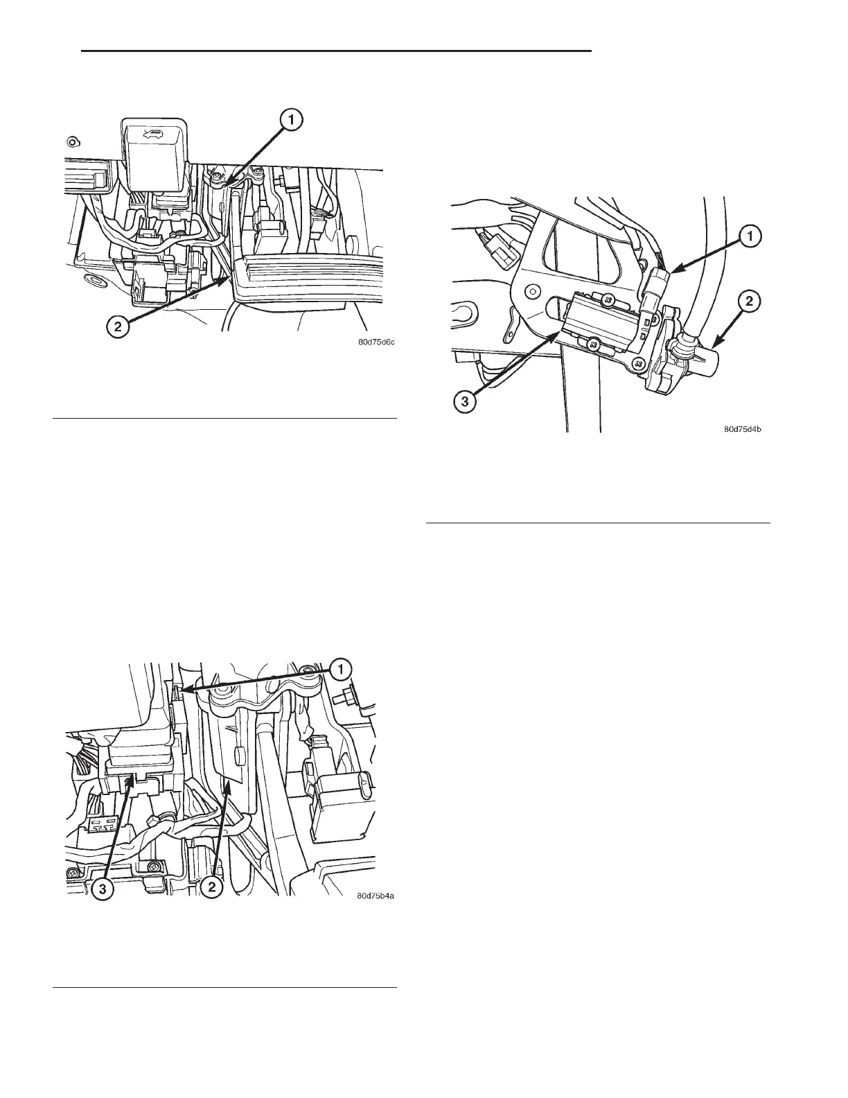
Fig. 10 Pedal Position Sensor Location
1 - PEDAL POSITION SENSOR
2 - BRAKE PEDAL
Fig. 11 Bulkhead Connector Release Tab
1 - RELEASE TAB
2 - PEDAL POSITION SENSOR
3 - BULKHEAD CONNECTOR
Fig. 12 Pedal Position Sensor
1 - WIRING CONNECTOR
2 - GEAR BOX
3 - PEDAL POSITION SENSOR
RS BRAKES - BASE 5-13
PEDAL POSITION SENSOR (Continued)