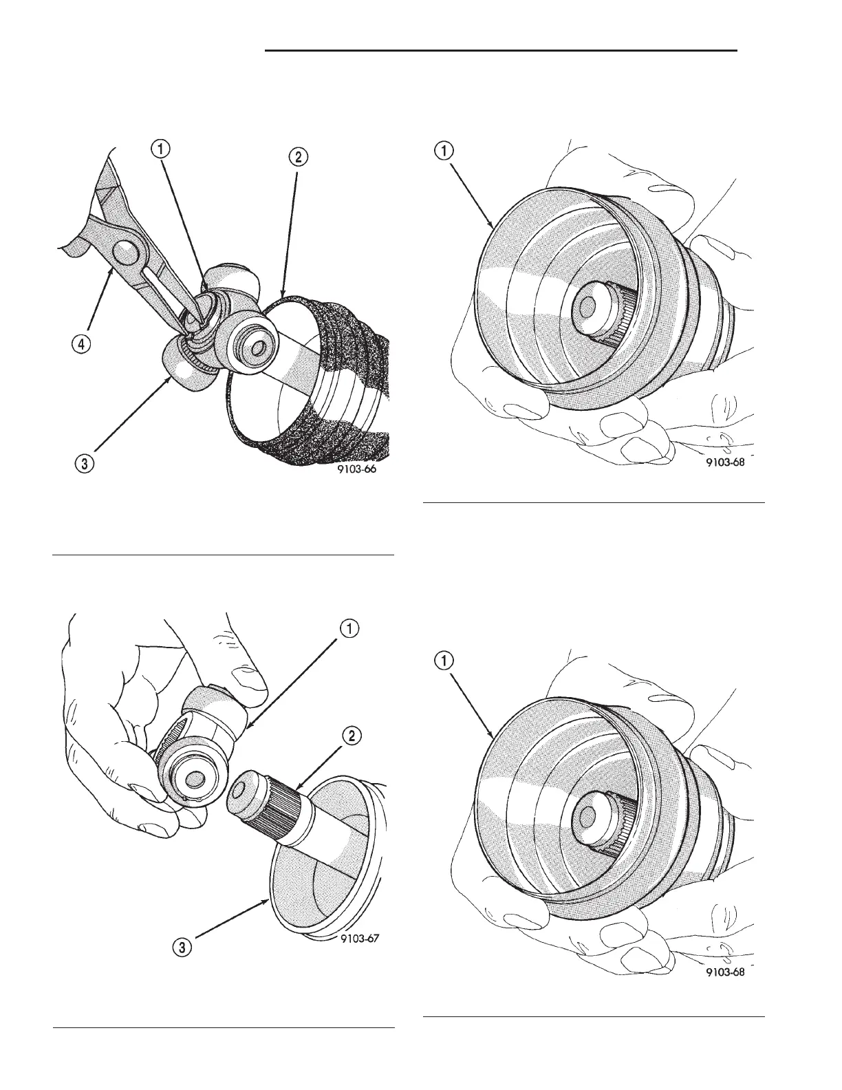
(6) Remove the snap-ring holding the tripod
assembly onto the interconnecting shaft (Fig. 11).
(7) Remove the tripod assembly from the intercon-
necting shaft (Fig. 12).
(8) Remove the CV boot from the interconnecting
shaft (Fig. 13).
INSTALLATION
(1) Clean the interconnecting shaft and inner CV
joint of any residual grease and dirt.
(2) Slide the new small diameter retaining clamp
onto the interconnecting shaft.
(3) Install the CV boot onto the interconnecting
shaft (Fig. 14).
Fig. 12 Slide Tripod Off The Shaft
1 - TRIPOD ASSEMBLY
2 - AXLE SHAFT
3 - HALF SHAFT BOOT
Fig. 11 Remove Snap-Ring
1 - SNAP RING
2 - HALF SHAFT BOOT
3 - TRIPOD ASSEMBLY
4 - SNAP RING PLIERS
Fig. 13 Remove Boot
1 - HALF SHAFT BOOT
Fig. 14 Install CV Boot Onto Interconnecting Shaft
1 - HALF SHAFT BOOT
3 - 18 HALF SHAFT - REAR RS
CV BOOT - INNER/OUTER (Continued)