(4) Install the battery in the vehicle. Refer to the
procedure in Battery Systems.
(5) Connect the positive and negative battery
cables.
(6) Using the DRB III t, under “FRONT CON-
TROL MODULE” then “MISC” program the EQ
curve of the radio into the Front Control Module.
Refer to the appropriate diagnostic manual.
NOTE: If the vehicle is not equipped with Name
Brand Speakers (Infinity, etc.) or Headlamp Washers
the DRB IIIT must be used to Disable the appropri-
ate relays in the Intelligent Power Module Assembly.
HEATED SEAT MODULE
DESCRIPTION
Vehicles equipped with heated seats utilize two
heated seat modules. The heated seat modules (Fig.
8) are located under the front seats, where they are
secured to the seat cushion pans. The left heated
seat module controls the left heated seat, and the
right controls the right. Each heated seat module has
three connector receptacles that allows the module to
be connected to all of the required inputs and out-
puts through the seat wire harness.
The heated seat module is an electronic micropro-
cessor controlled device designed and programmed to
use inputs from the ignition switch, heated seat
switch and the heated seat sensor to operate and
control the heated seat elements in the front seat
and the two heated seat indicator lamp Light-Emit-
ting Diodes (LEDs) in the heated seat switch.
The heated seat module cannot be repaired. If the
heated seat module is damaged or faulty, the entire
module must be replaced.
OPERATION
The heated seat module operates on fused battery
current received from the ignition switch and inte-
grated power module. The module is grounded at all
times through the seat wire harness. Inputs to the
module include a resistor multiplexed heated seat
switch request circuit for the heated seat switch and
the heated seat sensor inputs from the seat cushions
of each front seat. In response to those inputs the
heated seat module controls battery current feeds to
the heated seat elements, and controls the ground for
the heated seat switch indicator lamps.
When a heated seat switch request signal is
received by the heated seat module, the module ener-
gizes the proper indicator lamp (Low or High) in the
switch by grounding the indicator lamp circuit to
indicate that the heated seat system is operating. At
the same time, the heated seat module energizes the
selected heated seat sensor circuit and the sensor
provides the module with an input indicating the
surface temperature of the selected seat cushion.
The Low heat set point is about 38° C (100.4° F),
and the High heat set point is about 42° C (107.6° F).
If the seat cushion surface temperature input is
below the temperature set point for the selected tem-
perature setting, the heated seat module energizes
an N-channel Field Effect Transistor (N-FET) within
the module which energizes the heated seat elements
in the selected seat cushion and back. When the sen-
sor input to the module indicates the correct temper-
ature set point has been achieved, the module
de-energizes the N-FET which de-energizes the
heated seat elements. The heated seat module will
continue to cycle the N-FET as needed to maintain
the selected temperature set point.
DIAGNOSIS AND TESTING - HEATED SEAT
MODULE
If a heated seat fails to heat and one or both of the
indicator lamps on a heated seat switch flash, refer
to Diagnosis and Testing Heated Seat System in
Heated Seats for the location of flashing LED heated
seat system diagnosis and testing procedures. If a
heated seat heats but one or both indicator lamps on
the heated seat switch fail to operate, test the heated
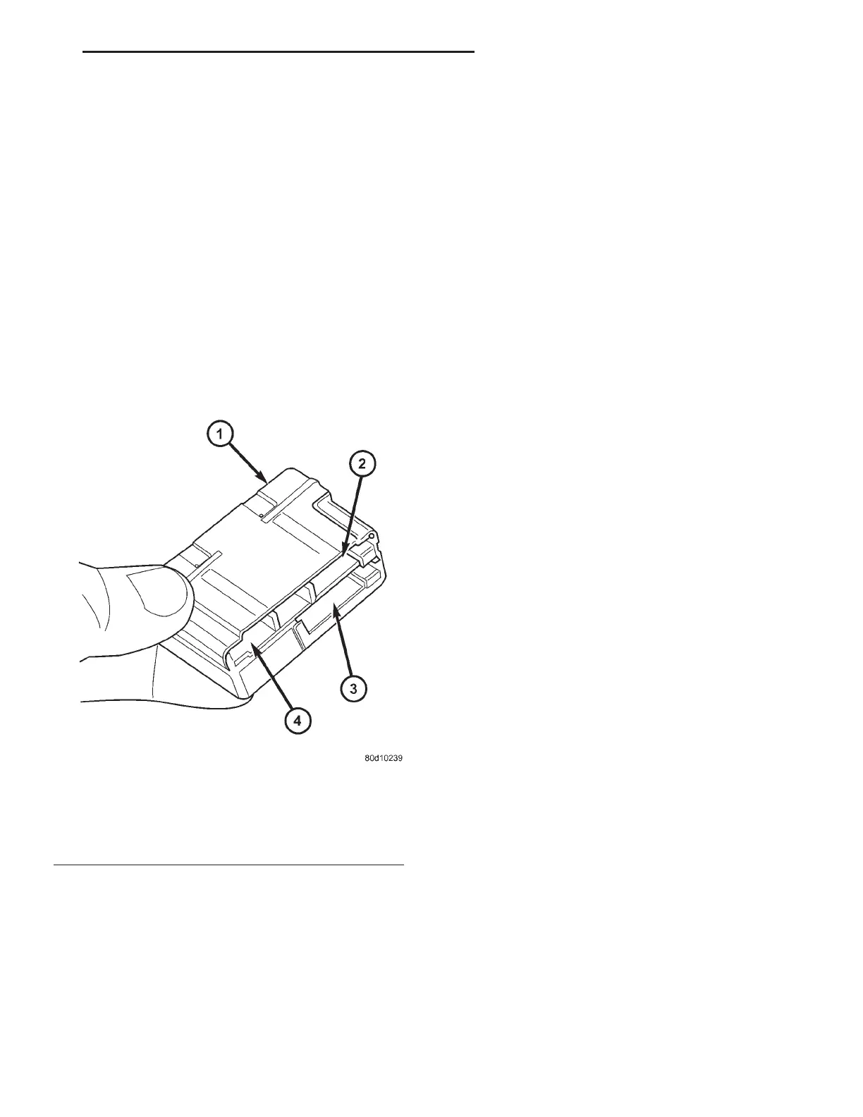
Fig. 8 RS/RG Heated Seat Modules
1 - HEATED SEAT MODULE
2 - C1 CONNECTOR
3 - C3 CONNECTOR
4 - C1 CONNECTOR
RS ELECTRONIC CONTROL MODULES 8E-9
FRONT CONTROL MODULE (Continued)