ELECTRONIC CONTROL MODULES
TABLE OF CONTENTS
page page
ENGINE CONTROL MODULE
DESCRIPTION ..........................1
OPERATION ............................1
STANDARD PROCEDURE - PCM/ECM/SKIM
PROGRAMMING - DIESEL ...............2
REMOVAL .............................4
INSTALLATION ..........................4
ENGINE CONTROL MODULE
DESCRIPTION
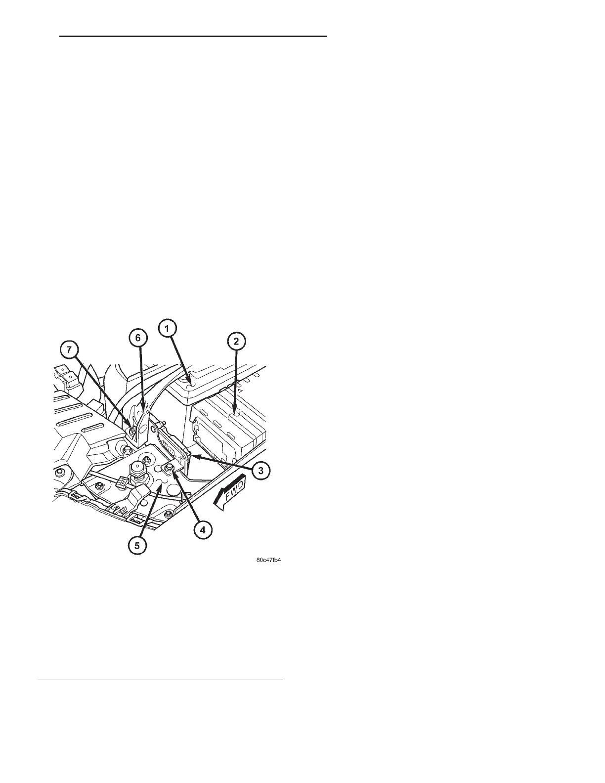
The ECM is located in the left front corner of the
engine compartment attached to the radiator support
(Fig. 1).
OPERATION
The ECM has been programmed to monitor differ-
ent circuits of the diesel fuel injection system. This
monitoring is called on-board diagnostics. Certain cri-
teria must be met for a diagnostic trouble code to be
entered into the ECM memory. The criteria may be a
range of: engine rpm, engine temperature, time or
other input signals to the ECM. If all of the criteria
for monitoring a system or circuit are met, and a
problem is sensed, then a DTC will be stored in the
ECM memory. It is possible that a DTC for a moni-
tored circuit may not be entered into the ECM mem-
ory, even though a malfunction has occurred. This
may happen when the monitoring criteria have not
been met. The ECM compares input signal voltages
from each input device with specifications (the estab-
lished high and low limits of the input range) that
are programmed into it for that device. If the input
voltage is not within the specifications and other
trouble code criteria are met, a DTC will be stored in
the ECM memory.
ECM OPERATING MODES
As input signals to the ECM change, the ECM
adjusts its response to the output devices. For exam-
ple, the ECM must calculate a different fuel quantity
and fuel timing for engine idle condition than it
would for a wide open throttle condition. There are
several different modes of operation that determine
how the ECM responds to the various input signals.
Ignition Switch On (Engine Off)
When the ignition is turned on, the ECM activates
the glow plug relay for a time period that is deter-
mined by engine coolant temperature, atmospheric
temperature and battery voltage.
Engine Start-Up Mode
The ECM uses the engine temperature sensor and
the crankshaft position sensor (engine speed) inputs
to determine fuel injection quantity.
Normal Driving Modes
Engine idle, warm-up, acceleration, deceleration
and wide open throttle modes are controlled based on
all of the sensor inputs to the ECM. The ECM uses
Fig. 1 ENGINE CONTROL MODULE LOCATION-
TYPICAL
1 - BATTERY
2 - IPM (INTEGRATED POWER MODULE)
3 - ECM (ENGINE CONTROL MODULE)
4 - RETAINING BOLT
5 - RADIATOR SUPPORT
6 - CLUTCH CABLE BRACKET (LHD)
7 - CLUTCH CABLE BRACKET RETAINING BOLT (LHD)
RG ELECTRONIC CONTROL MODULES 8Ea-1