system is receiving the proper hard wired inputs and
relaying the proper hard wired outputs to perform its
driver side power seat functions.
WARNING: SOME VEHICLES ARE EQUIPPED WITH
SEATBACK MOUNTED AIRBAGS. BEFORE
ATTEMPTING TO DIAGNOSE OR SERVICE ANY
SEAT OR POWER SEAT SYSTEM COMPONENT
YOU MUST FIRST DISCONNECT AND ISOLATE THE
BATTERY NEGATIVE CABLE. THEN WAIT TWO MIN-
UTES FOR THE SYSTEM CAPACITOR TO DIS-
CHARGE BEFORE FURTHER SYSTEM SERVICE.
THIS IS THE ONLY SURE WAY TO DISABLE THE
AIRBAG SYSTEM. FAILURE TO DO SO COULD
RESULT IN ACCIDENTAL AIRBAG DEPLOYMENT
AND POSSIBLE PERSONAL INJURY.
(1) If the driver power seat exhibits a interrupted
or jerky motion, there is a possibility that the wires
leading from the memory seat module to the memory
seat motor are mis-wired. To check the concern,
obtain a DRB IIIt scan tool and energize each axis
one at a time. If any axis stops in approximately 2
seconds (without hitting the end of travel), the feed-
back for that axis may have an open, short or be mis-
wired. Check the wiring to that axis (module to
motor). Fix any wiring problems and retry that axis.
(2) If any power seat is not operational in any
direction, check the power seat circuit breaker,
located under the trailing edge of the appropriate
power seat. Refer to the Power Distribution section of
this service manual for the circuit breaker diagnosis
and testing procedure.
(3) If the power seat circuit breaker is OK, check
for proper 12v and ground connections at the power
seat switch and/or memory seat module. Fix any wir-
ing problems and retry.
(4) Check the power seat system wire harness con-
nections and pins to ensure proper circuit continuity
and ground paths. For complete circuit diagrams,
refer to Wiring Diagrams.
(5) With the dome lamp on, apply the power seat
switch in the direction of the failure. If the dome
lamp dims, the seat may be jamming. Check under
and behind the seat for binding or obstructions. If
the dome lamp does not dim, proceed with testing of
the individual components and circuits in the power
seat system.
DIAGNOSIS AND TESTING - MEMORY SYSTEM
In order to obtain conclusive testing of the memory
system, the Programmable Communications Interface
(PCI) data bus network and all of the electronic mod-
ules that provide inputs to, or receive outputs from
the memory system components must be checked.
The most reliable, efficient, and accurate means to
diagnose the memory system requires the use of a
DRB IIIt scan tool and the proper Diagnostic Proce-
dures manual. The DRB IIIt scan tool can provide
confirmation that the PCI data bus is functional, that
all of the electronic modules are sending and receiv-
ing the proper messages on the PCI data bus, and
that the memory system is receiving the proper hard
wired inputs and relaying the proper hard wired out-
puts to perform its functions.
(1) If the driver power seat exhibits a interrupted
or jerky motion, there is a possibility that the wires
leading from the memory seat module to the memory
seat motor are mis-wired. To check the concern,
obtain a DRB IIIt scan tool and energize each axis
one at a time. If any axis stops in approximately 2
seconds (without hitting the end of travel), the feed-
back for that axis may have an open, short or be mis-
wired. Check the wiring to that axis (module to
motor). Fix any wiring problems and retry that axis.
Refer to Wiring Diagrams for complete circuit sche-
matic or connector pin-out information.
DRIVER SEAT SWITCH
DESCRIPTION
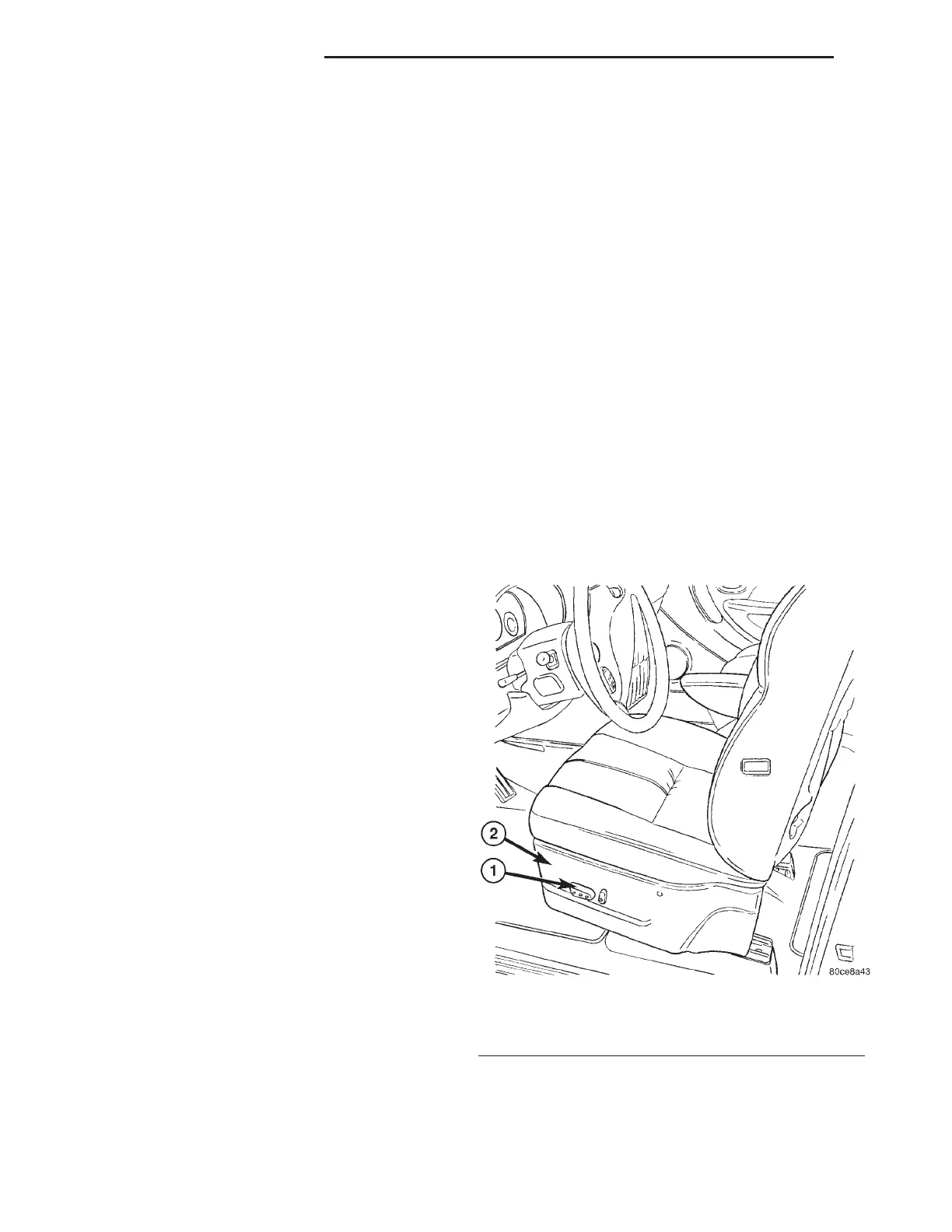
Vehicles equipped with power seats utilize a eight-
way power seat switch. This eight-way power seat
switch features two knobs ganged together on the
outboard seat cushion side shield (Fig. 2).
Fig. 2 Power Seat Switch Location
1 - Power Seat Switch
2 - Seat Cushion Side Shield
8N - 54 POWER SEAT SYSTEM RS
POWER SEAT SYSTEM (Continued)






 To Next Page