(3) Install the four chassis brake tubes into the
outlet ports of the junction block. Tighten all 6 tube
nuts to a torque of 17 N·m (145 in. lbs.).
(4) If the vehicle is equipped with speed control,
perform the following:
(a) Install the speed control servo with its
mounting nuts.
(b) Connect the wiring harness to the speed con-
trol servo.
(c) Install the battery tray (Refer to 8 - ELEC-
TRICAL/BATTERY SYSTEM/TRAY - INSTALLA-
TION).
(d) Install the screw securing the coolant filler
neck to the battery tray.
(e) Reconnect the vacuum hose connector at the
tank built into the battery tray.
(f) Install the battery (Refer to 8 - ELECTRI-
CAL/BATTERY SYSTEM/BATTERY - INSTALLA-
TION).
(g) Install the battery shield.
(5) Remove the brake pedal holder.
(6) Connect negative cable back on negative post of
the battery.
(7) Bleed the brake system thoroughly to ensure
that all air has been expelled from the hydraulic sys-
tem. (Refer to 5 - BRAKES - STANDARD PROCE-
DURE).
(8) Road test the vehicle to verify proper operation
of the brake system.
MASTER CYLINDER
DESCRIPTION
DESCRIPTION
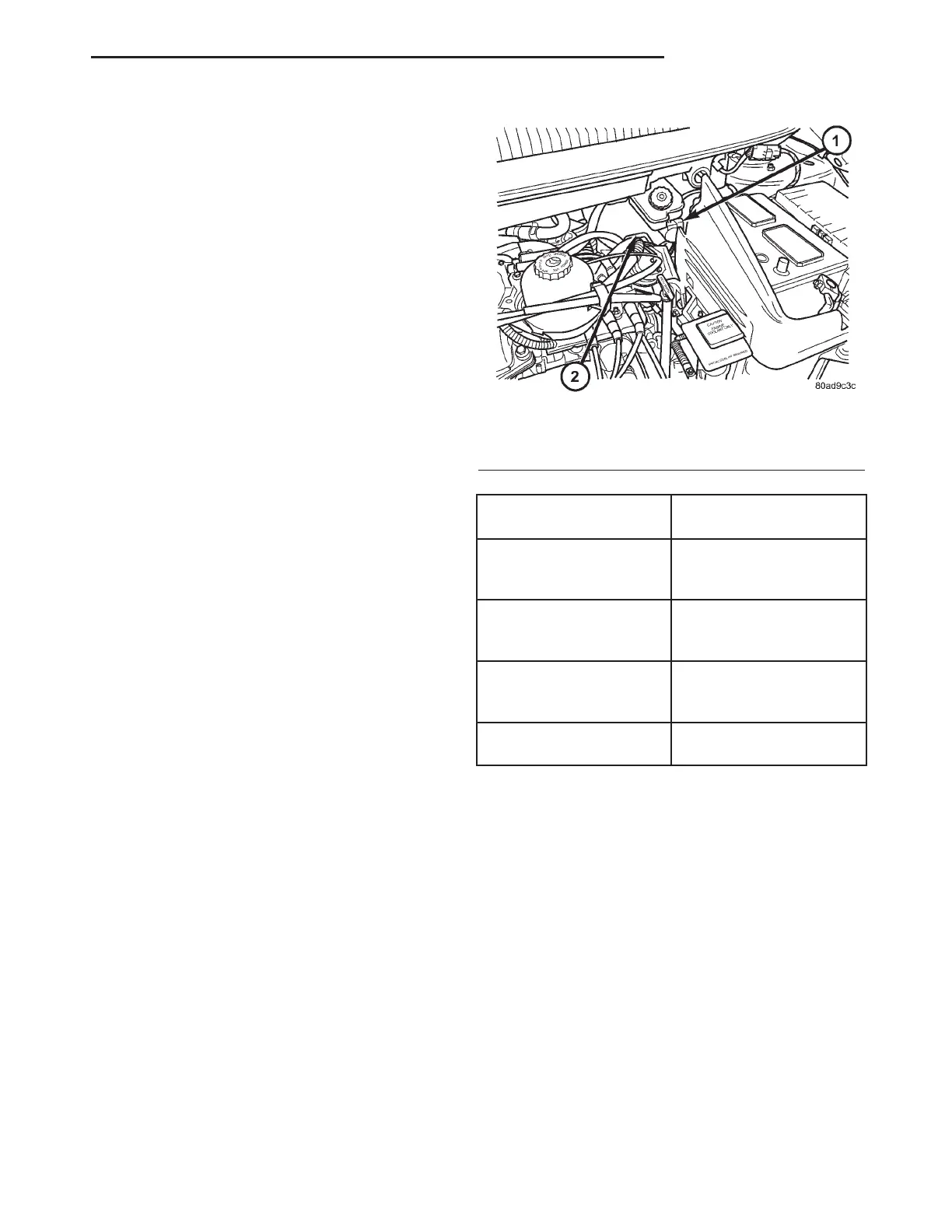
The master cylinder is located on the power brake
booster in the engine compartment on the driver’s
side (Fig. 54). This vehicle uses 3 different master
cylinders. Master cylinder usage depends on what
type of brake system the vehicle is equipped with.
CAUTION: Master cylinders are not interchangeable
between systems. Performance and stopping dis-
tance issues will result if the incorrect master cyl-
inder is installed on the vehicle.
For information on master cylinder application,
bore and type, view the following table:
BRAKE SYSTEM
MASTER CYLINDER
BORE/TYPE
Disc/Drum - ABS
23.8 mm (15/16 in.)
Conventional
Compensating Port
Disc/Drum - Non-ABS
23.8 mm (15/16 in.)
Conventional
Compensating Port
Disc/Disc - ABS
27.0 mm (1-1/16 in.)
Conventional
Compensating Port
Disc/Disc ABS With
Traction Control
27.0 mm (1-1/16 in.) Dual
Center Port
CAUTION: When replacing a master cylinder, be
sure to use the correct master cylinder for the type
of brake system the vehicle is equipped with.
The body of the master cylinder is an anodized alu-
minum casting. It has a machined bore to accept the
master cylinder pistons and threaded ports with
seats for the hydraulic brake line connections.
The brake fluid reservoir is mounted on the top of
the master cylinder. It is made of a see-through
polypropylene type plastic for easy fluid level view-
ing. A brake fluid level switch is attached to the
brake fluid reservoir.
The master cylinder is not a repairable component
and must be replaced if diagnosed to be functioning
improperly. The brake fluid reservoir and brake fluid
level switch can be replaced separately.
Fig. 54 Master Cylinder And Booster Location
1 - MASTER CYLINDER
2 - POWER BRAKE BOOSTER
RS BRAKES - BASE 5-37
JUNCTION BLOCK (Continued)