CHECKING SWITCH ONLY
(1) Disconnect and isolate the battery negative
cable. Remove the center bezel from the instrument
panel (Refer to 23 - BODY/INSTRUMENT PANEL/
INSTRUMENT PANEL CENTER BEZEL - REMOV-
AL). Check for continuity between the ground circuit
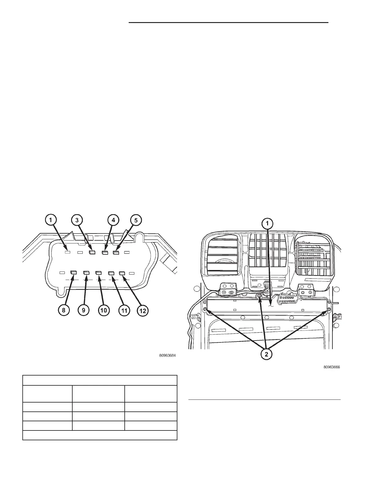
cavity (#10) of the instrument panel switch bank
electrical connector and a good ground. There should
be continuity. If OK, go to Step 2. If not OK, repair
the open ground circuit to ground as required.
(2) Reconnect the battery negative cable. Turn the
ignition switch to the On position. Check for battery
voltage at the fused ignition switch output (run) cir-
cuit cavity of the instrument panel switch bank con-
nector (#4). If OK, turn the ignition switch to the Off
position, and go to Step 3. If not OK, repair the open
fused ignition switch output (run) circuit as required.
(3) Test the heated seat switch as shown in the
Heated Seat Switch Test chart and the connector pin-
out below (Fig. 3). If OK, go to Step 4. If not OK,
replace the faulty switch bank assembly.
DRIVER HEATED SEAT SWITCH TEST
SWITCH
POSITION
RESISTANCE
BETWEEN
RESISTANCE
(OHMS)
Off Pin4&5 OPEN
Low Pin4&5 3570
High Pin4&5 1430
All resistance values are ±1%.
(4) Reconnect the instrument panel switch bank
and test the heated seat system for proper operation.
If the system is still inoperative proceed with check-
ing remaining components.
REMOVAL
WARNING: ON VEHICLES EQUIPPED WITH AIR-
BAGS, REFER TO THE RESTRAINTS SECTION OF
THIS MANUAL BEFORE ATTEMPTING ANY STEER-
ING WHEEL, STEERING COLUMN, SEAT OR
INSTRUMENT PANEL COMPONENT DIAGNOSIS OR
SERVICE. FAILURE TO TAKE THE PROPER PRE-
CAUTIONS COULD RESULT IN ACCIDENTAL AIR-
BAG DEPLOYMENT AND POSSIBLE PERSONAL
INJURY.
(1) Disconnect and isolate the battery negative
cable.
(2) Remove the instrument panel center bezel.
Refer to Instrument Panel Center Bezel in the
Body section for the procedure.
(3) Remove the three screws (Fig. 4) that secure
the heated seat switch to the back of the instrument
panel center bezel.
(4) Remove the heated seat switch from the back
of the instrument panel center bezel.
INSTALLATION
(1) Position the heated seat switch onto the back
of the instrument panel center bezel.
Fig. 3 Instrument Panel Switch Bank Connector
Fig. 4 SWITCH RETAINING SCREWS
1 - HEATED SEAT SWITCH ASSEMBLY
2 - RETAINING SCREWS
8G - 10 HEATED SEAT SYSTEM RS
DRIVER HEATED SEAT SWITCH (Continued)