The switch is secured to the back of the seat cush-
ion side shield with two screws. However, the control
knobs for the seat switch unit must be removed
before the seat switch can be removed from the side
shield.
The power seat switch cannot be repaired. If one
switch is damaged or faulty, the entire power seat
switch unit must be replaced.
OPERATION
When a power seat switch control knob or knobs
are actuated, a battery feed and a ground path are
applied through the switch contacts to the power seat
track or recliner adjuster motor. The selected
adjuster motor operates to move the seat track or
recliner through its drive unit in the selected direc-
tion until the switch is released, or until the travel
limit of the adjuster is reached. When the switch is
moved in the opposite direction, the battery feed and
ground path to the motor are reversed through the
switch contacts. This causes the adjuster motor to
run in the opposite direction.
No power seat switch should be held applied in any
direction after the adjuster has reached its travel
limit. The power seat adjuster motors each contain a
self-resetting circuit breaker to protect them from
overload. However, consecutive or frequent resetting
of the circuit breaker must not be allowed to con-
tinue, or the motor may be damaged. See the owner’s
manual in the vehicle glove box for more information
on the power seat switch functions and the seat
adjusting procedures.
DIAGNOSIS AND TESTING - DRIVER SEAT
SWITCH
(1) Remove the power seat switch, refer to the
Switch Removal and Installation procedures in this
section.
(2) Using an ohmmeter, check pin #1 of the power
seat switch connector for continuity to ground. It
should be present, If OK go to Step3,IfNOTOK
repair the open ground circuit as required.
(3) Using an voltmeter, check pin #5 of the power
seat switch connector for approx. 12v. It should be
present, If OK go to Step4,IfNOTOKrepair the
open voltage supply circuit as required.
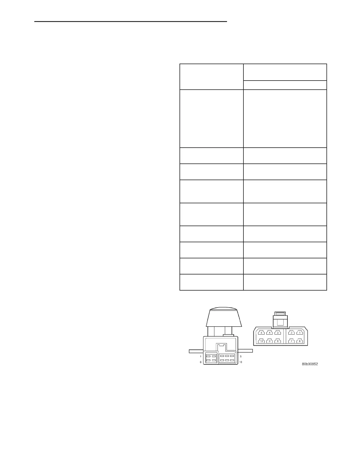
(4) Using an ohmmeter, verify the Seat Switch
Continuity Test table, using the seat switch connec-
tor (Fig. 3). If there is no continuity at any of the
switch positions, replace the power seat switch.
DRIVER SEAT SWITCH CONTINUITY TEST
TABLE
SWITCH
POSITION
CONTINUITY BETWEEN
PINS
DRIVER
OFF PIN5&4
PIN5&3
PIN5&2
PIN5&10
PIN5&9
PIN5&8
PIN5&7
PIN5&6
FRONT RISER
UP
PIN5&6
PIN1&9
FRONT RISER
DOWN
PIN5&9
PIN1&6
CENTER
SWITCH
FORWARD
PIN5&3
PIN1&10
CENTER
SWITCH
REARWARD
PIN5&10
PIN3&1
REAR RISER UP PIN5&7
PIN1&8
REAR RISER
DOWN
PIN5&8
PIN1&7
RECLINER UP PIN5&2
PIN4&1
RECLINER
DOWN
PIN5&4
PIN2&1
REMOVAL
(1) Disconnect and isolate the battery negative
cable.
(2) On models equipped with the eight-way power
seat, using a push pin remover or another suitable
wide flat-bladed tool, gently pry the power seat and
power recliner switch knobs off of the switch levers
(Fig. 4).
Fig. 3 Seat Switch Pin Call-Out
RS POWER SEAT SYSTEM 8N-55
DRIVER SEAT SWITCH (Continued)