INSTALLATION
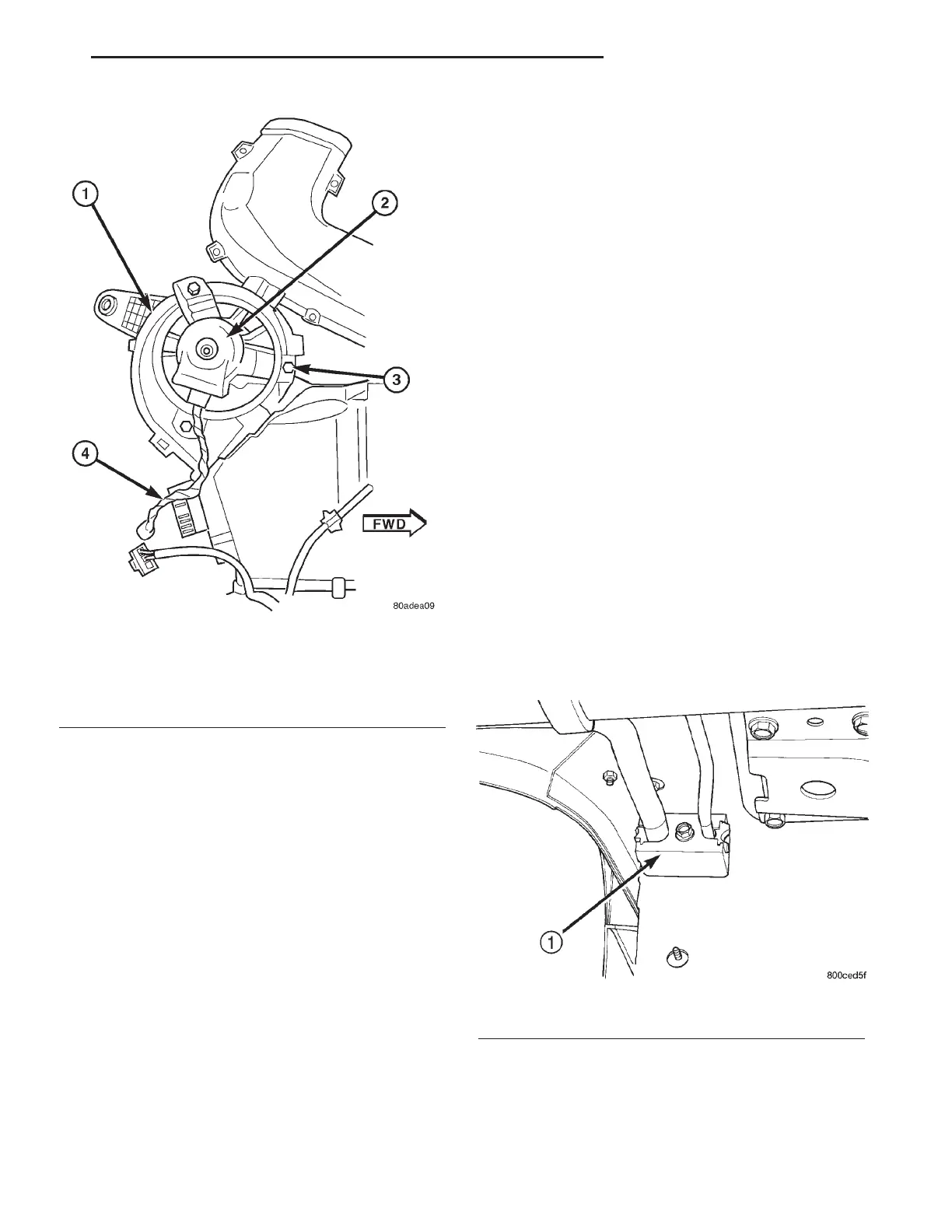
(1) Position the blower motor and blower wheel
onto the outboard side of the rear heater-A/C unit
housing.
(2) Install and tighten the three screws that secure
the blower motor to the rear heater-A/C unit housing.
Tighten the screws to 2 N·m (18 in. lbs.).
(3) Reconnect the rear blower motor pigtail wire
connector. With manual temperature control, the
blower pigtail wire is connected to a take out and
connector of the rear HVAC wire harness. With auto-
matic temperature control, the blower pigtail wire is
connected to a receptacle on the blower power mod-
ule.
(4) Reinstall the rear heater-A/C unit housing into
the vehicle. (Refer to 24 - HEATING & AIR CONDI-
TIONING/DISTRIBUTION - REAR/REAR HEATER-
A/C HOUSING - INSTALLATION).
REAR HEATER-A/C HOUSING
REMOVAL
WARNING: REFER TO THE APPLICABLE WARN-
INGS AND CAUTIONS FOR THIS SYSTEM BEFORE
PERFORMING THE FOLLOWING OPERATION.
(Refer to 24 - HEATING & AIR CONDITIONING/
PLUMBING - FRONT - WARNING - A/C PLUMBING),
(Refer to 24 - HEATING & AIR CONDITIONING/
PLUMBING - FRONT - CAUTION - A/C PLUMBING),
and (Refer to 24 - HEATING & AIR CONDITIONING/
PLUMBING - FRONT - WARNING - HEATER PLUMB-
ING).
(1) Recover the refrigerant from the refrigerant
system. (Refer to 24 - HEATING & AIR CONDI-
TIONING/PLUMBING - FRONT/REFRIGERANT -
STANDARD PROCEDURE - REFRIGERANT
RECOVERY).
(2) Drain the engine cooling system. (Refer to 7 -
COOLING - STANDARD PROCEDURE - COOLING
SYSTEM DRAIN).
(3) Disconnect and isolate the battery negative
cable.
(4) Raise and support the vehicle.
(5) Disconnect the underbody refrigerant line seal-
ing plate from the rear heater-A/C unit evaporator
extension line sealing plate that extends through the
rear floor panel behind the right rear wheel housing
(Fig. 6).
(6) Remove the seals from the liquid line and suc-
tion line fittings and discard.
(7) Install plugs in, or tape over the opened liquid
line and suction line fittings and both ports in the
evaporator extension line sealing plate.
Fig. 5 Blower Motor
1 - REAR HEATER-A/C UNIT HOUSING
2 - BLOWER MOTOR
3 - SCREW (3)
4 - BLOWER PIGTAIL WIRE
Fig. 6 Refrigerant Lines
1 - UNDERBODY REFRIGERANT LINE SEALING PLATE
RS DISTRIBUTION - REAR 24-55
BLOWER MOTOR (Continued)










 To Next Page