(12) Slowly release the tension from the coil spring
by backing off the compressor drive fully. As the ten-
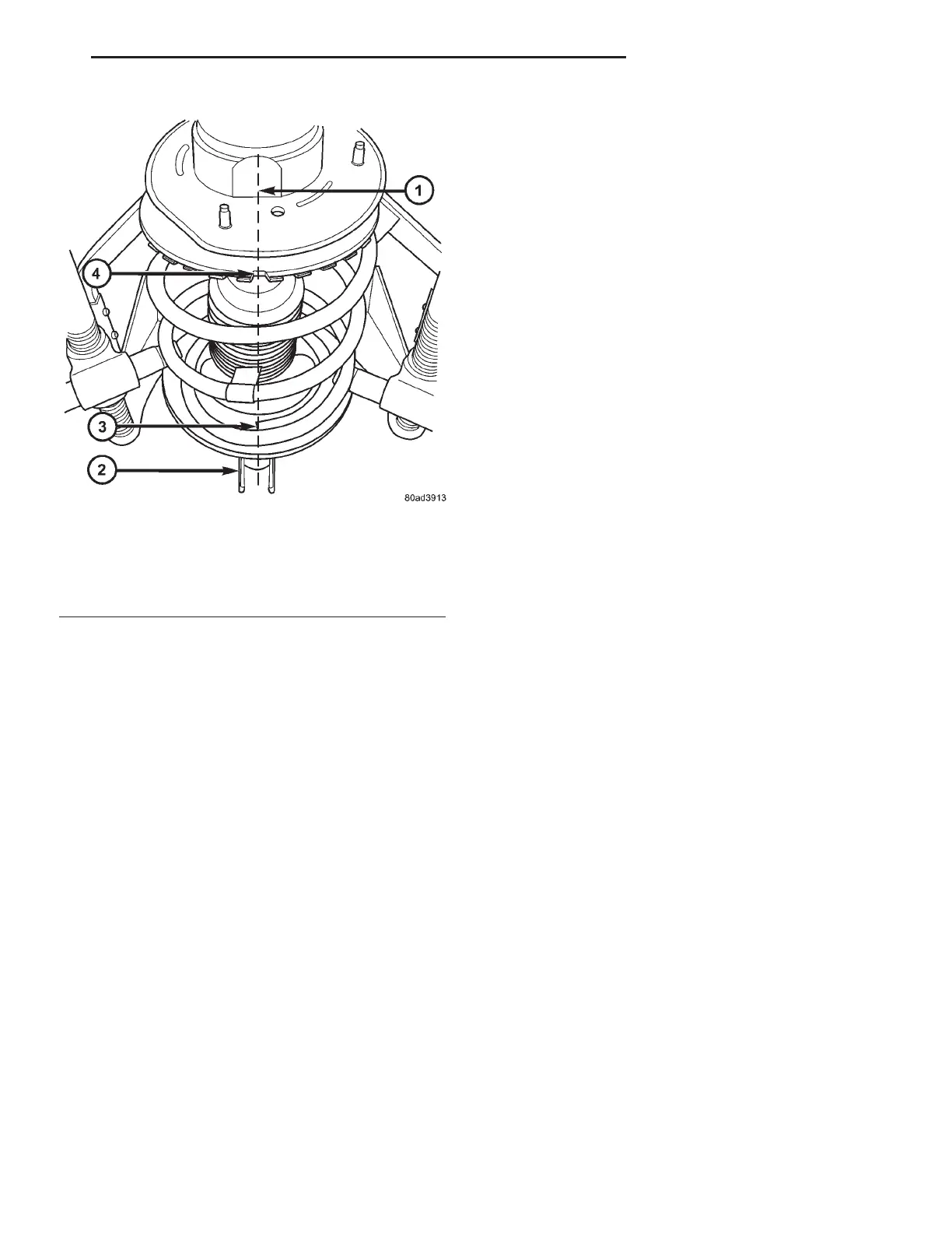
sion is relieved, make sure the upper mount, pivot
bearing and upper seat are align properly. Remove
the clamp from the lower end of the coil spring and
strut. Push back the spring compressor upper and
lower hooks, then remove the strut assembly from
the spring compressor.
(13) Install strut assembly on the vehicle. (Refer to
2 - SUSPENSION/FRONT/STRUT - INSTALLA-
TION)
INSTALLATION - STRUT ASSEMBLY
CAUTION: Front strut coil springs are side-oriented.
When installing a strut assembly, make sure the
strut being installed has the correct coil spring for
that side of the vehicle. Springs on the left side of
the vehicle have a left-hand wind top-to-bottom
while springs on the right side have a right-hand
wind top-to-bottom (Fig. 49). Do not interchange the
two sides.
(1) Install strut assembly into strut tower, aligning
and installing the 3 studs on the upper strut mount
into the holes in shock tower. Install the 3 upper
strut mount attaching nut/washer assemblies (Fig.
43). Then using a crow foot. tighten the 3 attaching
nuts to a torque of 28 N·m (250 in. lbs.).
CAUTION: The steering knuckle to strut assembly
attaching bolts are serrated and must not be turned
during installation. Install nuts while holding bolts
stationary in the steering knuckles.
NOTE: The strut clevis-to-steering knuckle bolts are
installed differently on each side of the vehicle. Left
hand side bolts are to be installed from vehicle rear
to front. Right side bolts are to be installed from
vehicle front to rear.
(2) Align strut assembly with steering knuckle.
Position arm of steering knuckle into strut assembly
clevis bracket. Align the strut assembly clevis
bracket mounting holes with the steering knuckle
mounting holes. Install the 2 strut assembly to steer-
ing knuckle attaching bolts (Fig. 42). If strut assem-
bly is attached to steering knuckle using a cam
bolt, the cam bolt must be installed in the lower
slotted hole on strut clevis bracket. Tighten the
strut clevis-to-steering knuckle attaching bolts to a
torque of 81 N·m (60 ft. lbs.) plus an additional 1/4
(90°) turn after specified torque is met.
(3) Install the stabilizer bar link mounting stud
through the bracket on the strut assembly (Fig. 41).
CAUTION: When installing the nut on the mounting
stud of the stabilizer bar link, do not allow the stud
to rotate in it’s socket. Hold the stud from rotating
by placing an open-end wrench on the flat
machined into the stud (Fig. 41).
(4) Hand thread the nut on the end of the stabi-
lizer bar link stud. Hold the stud from turning by
placing an open-end wrench on the flat machined
into the link’s mounting stud, then tighten the nut
while holding the wrench in place (Fig. 41). Tighten
the nut to a torque of 88 N·m (65 ft. lbs.).
(5) Install the hydraulic brake hose and speed sen-
sor cable routing brackets on the strut assembly
brackets (Fig. 40). Tighten the routing bracket
attaching bolts to a torque of 13 N·m (10 ft. lbs.).
(6) Install the wheel/tire assembly on the vehicle.
(7) Install and tighten the wheel mounting stud
nuts in proper sequence until all nuts are torqued to
half specification. Then repeat the tightening
sequence to the full specified torque of 135 N·m (100
ft. lbs.).
Fig. 50 Components Lined Up
1 - IMAGINARY VERTICAL LINE
2 - CLEVIS BRACKET
3 - END OF COIL SPRING
4 - NOTCH IN UPPER SPRING SEAT
RS FRONT SUSPENSION 2-25
STRUT (Continued)