Use a known good vehicle for side door comparison
data. Refer to the Side Door Adjustment procedure in
the Body section of the service manual for detailed
instructions.
LATCH
DESCRIPTION
Vehicles equipped with a power side door or doors
utilize a power latch. One power latch is used for
each power door. The latch is located on the trailing
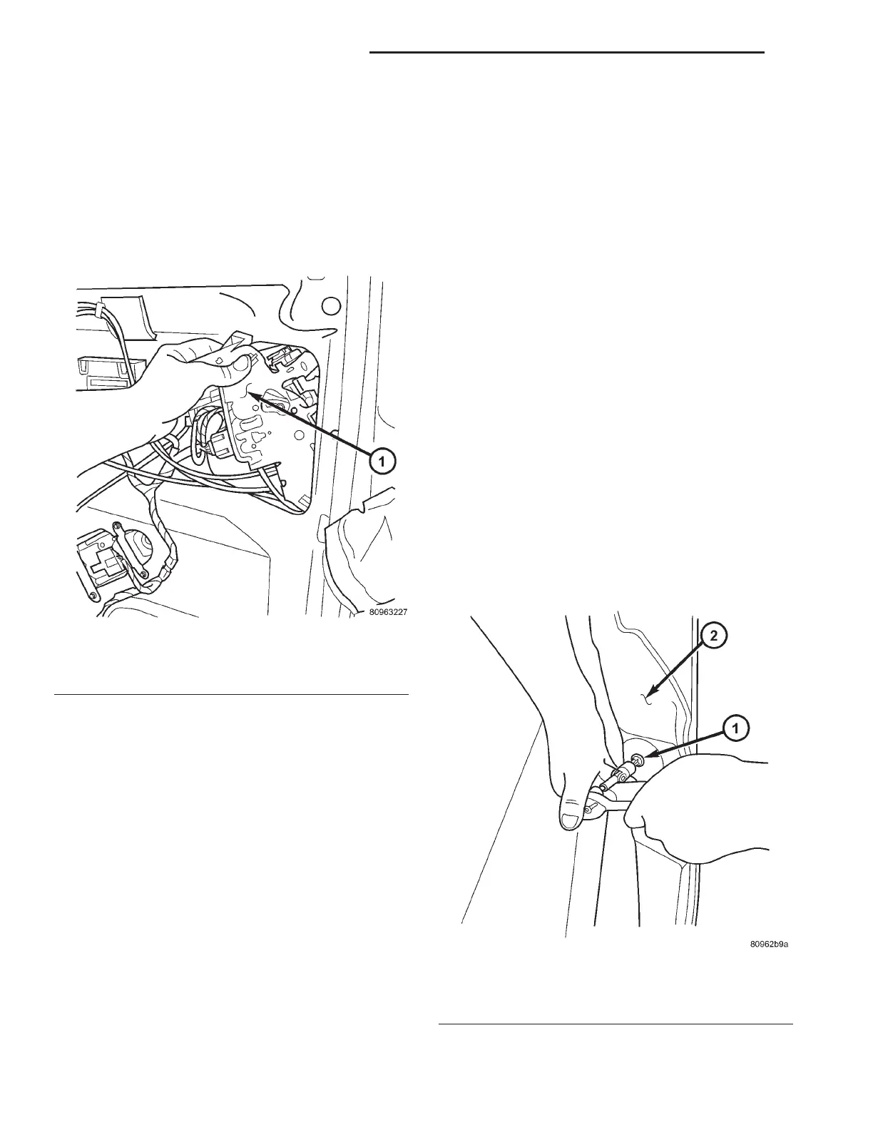
edge of the side door assembly (Fig. 5). This power
latch assembly is comprised of many different compo-
nents which have the ability to perform the power
cinch, release, lock, unlock and safety related opera-
tions. These components are the door latch, lock/un-
lock actuator, cinch/release actuator and child
lockout, pawl, ratchet and handle switches. The pawl
and ratchet switches are used to indicate the primary
and secondary latched positions. The cinch latch also
provides a connection point for the interior handle,
exterior handle and hold open latch cables.
The power latch is a replaceable component. Con-
sult your Mopar parts catalog for specific part num-
bers.
OPERATION
The power latch performs the same operation as a
full manual door latch as well as power cinch,
release, lock and unlock operations. The power latch
mounted actuator cinches the door closed and latches
it in its primary latched position. During a power
close cycle, the power cinch actuator will not operate
until the side door has reached its secondary latch
position (determined by pawl and ratchet switches).
During a power open cycle, the power release actua-
tor will stop once the side door has moved from pri-
mary latch position.
The power latch uses inputs from the lock/unlock
actuator, power side door control module and child
lockout, pawl, ratchet and handle switches to provide
safe power cinch and release operations. Refer to
Power Side Door Operation for additional informa-
tion.
REMOVAL
(1) Disconnect and isolate the negative battery
cable.
(2) Remove the appropriate side door trim panel.
Refer to the Body section for the procedure.
(3) Remove the weather shield if necessary. Refer
to the Body section for the procedure.
(4) Open the side door all the way and remove the
door latch retaining bolts (Fig. 6).
Fig. 5 Removing/Installing Power Latch in Sliding
Door
1 - Power Latch Assembly
Fig. 6 Removing Latch Retaining Bolts
1 - Latch Retaining Bolts
2 - Side Door
8N - 28 POWER SLIDING DOOR SYSTEM RS
POWER SLIDING DOOR SYSTEM (Continued)










 To Next Page