DIAGNOSIS AND TESTING - HUB AND
BEARING
The condition of the front hub and bearing assem-
bly is diagnosed using the inspection and testing pro-
cedure detailed below.
The bearing contained in the Unit III front hub/
bearing assembly will produce noise and vibration
when worn or damaged. The noise will generally
change when the bearings are loaded. A road test of
the vehicle is normally required to determine the
location of a worn or damaged bearing.
Find a smooth level road surface and bring the
vehicle up to a constant speed. When vehicle is at a
constant speed, swerve the vehicle back and forth
from the left and to the right. This will load and
unload the bearings and change the noise level.
When bearing damage is slight, the noise is some-
times noticeable at lower speeds and at other times
is more noticeable at speeds above 105 km/h (65
mph).
REMOVAL
NOTE: Replacement of the Unit III front hub/bearing
assembly can be normally done without having to
remove the steering knuckle from the vehicle. In the
event that the hub/bearing is frozen in the steering
knuckle and cannot be removed by hand, it will
have to be pressed out of the steering knuckle. The
steering knuckle will require removal from the vehi-
cle to allow the hub/bearing assembly to be
pressed out of the steering knuckle. (Refer to 2 -
SUSPENSION/FRONT/KNUCKLE - REMOVAL)
(1) Raise vehicle. (Refer to LUBRICATION &
MAINTENANCE/HOISTING - STANDARD PROCE-
DURE)
(2) Remove wheel lug nuts, and front tire and
wheel assembly.
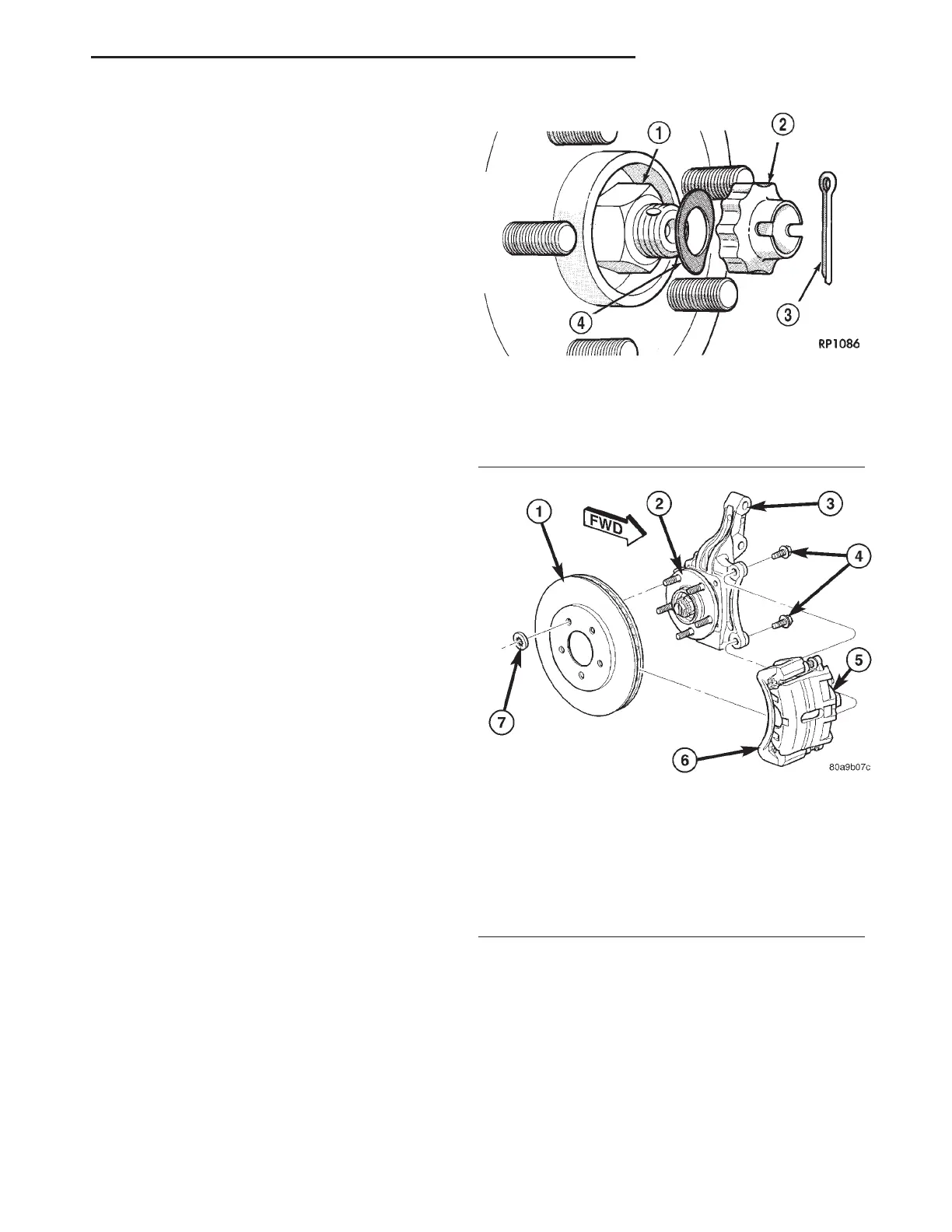
(3) Remove the cotter pin, nut lock and spring
washer from the stub axle (Fig. 4).
(4) With aid of a helper applying the brakes to
keep the front hub from turning, remove the hub nut
(Fig. 4).
(5) Remove disc brake caliper and adapter as an
assembly from knuckle as shown (Fig. 5). Hang
assembly out of the way using a bungee cord or wire.
Do not allow caliper hang by brake hose.
(6) Remove brake rotor from hub and bearing (Fig.
5).
(7) Push in on end of driveshaft stub shaft, push-
ing its splines out of the hub splines.
(8) Remove the four hub and bearing mounting
bolts from the rear of steering knuckle (Fig. 6). Use
care not to come in contact with and damage
the ABS tone wheel on the driveshaft stub shaft
upon bolt removal.
(9) Remove the hub and bearing assembly from
the steering knuckle.
Fig. 4 Hub Nut
1 - HUB NUT
2 - NUT LOCK
3 - COTTER PIN
4 - SPRING WASHER
Fig. 5 Front Brake Mounting
1 - BRAKE ROTOR
2 - HUB AND BEARING
3 - STEERING KNUCKLE
4 - ADAPTER MOUNTING BOLTS
5 - BRAKE CALIPER
6 - ADAPTER
7 - CLIP
RS FRONT SUSPENSION 2-5
HUB / BEARING (Continued)