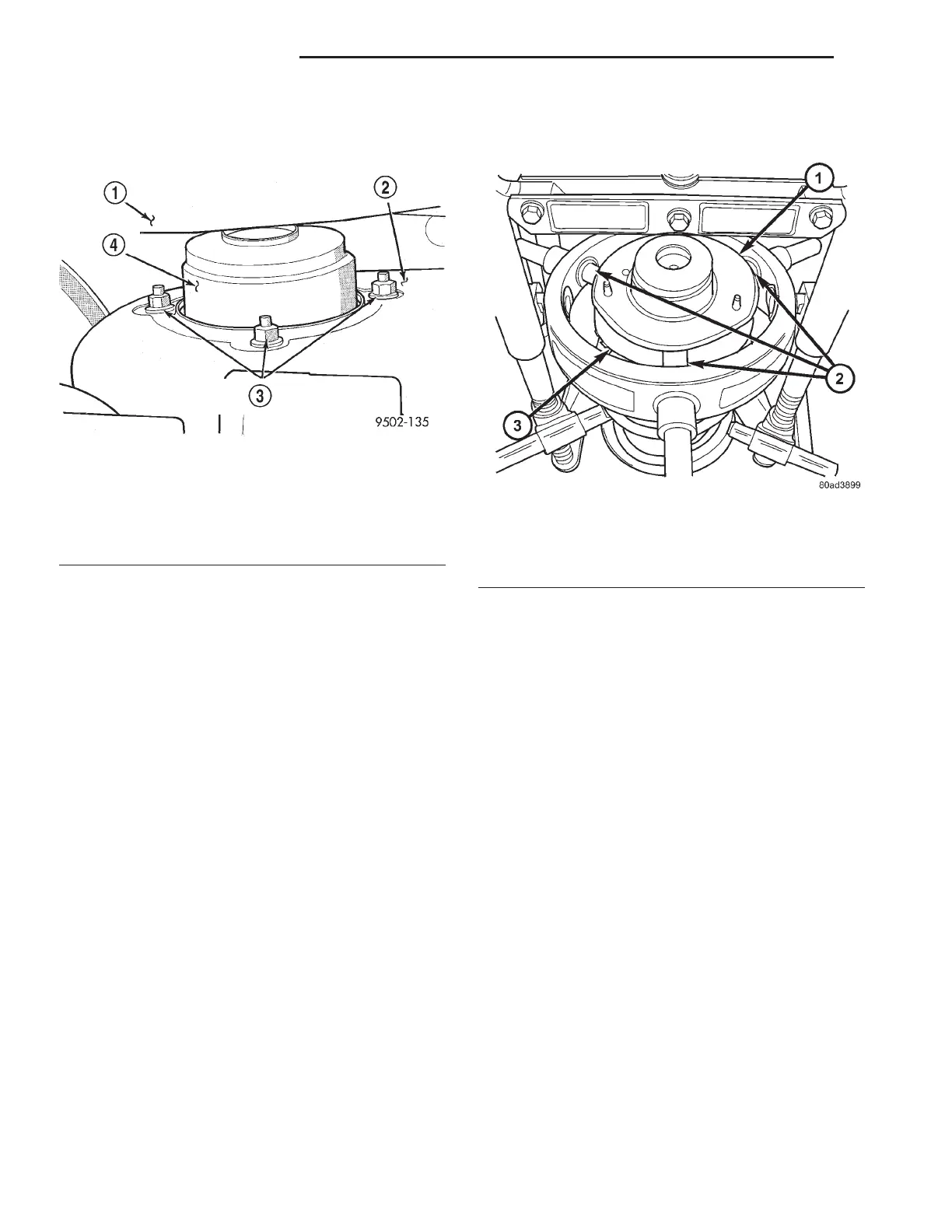
(7) Remove the 3 nuts attaching the strut assem-
bly upper mount to the strut tower (Fig. 43) and
remove the strut assembly from the vehicle.
(8) To disassemble the strut assembly, (Refer to 2 -
SUSPENSION/FRONT/STRUT - DISASSEMBLY).
DISASSEMBLY - STRUT ASSEMBLY
The strut assembly must be removed from the
vehicle for it to be disassembled and assembled.
For the disassembly and assembly of the strut
assembly, use of Strut Spring Compressor, Pentastar
Service Equipment (PSE) tool W-7200, or the equiva-
lent, is recommended to compress the coil spring.
Follow the manufacturer’s instructions closely.
WARNING: DO NOT REMOVE THE STRUT SHAFT
NUT BEFORE THE COIL SPRING IS COMPRESSED.
THE COIL SPRING IS HELD UNDER PRESSURE
AND MUST BE COMPRESSED, REMOVING SPRING
TENSION FROM THE UPPER MOUNT AND PIVOT
BEARING, BEFORE THE SHAFT NUT IS REMOVED.
(1) Position the strut assembly in the strut coil
spring compressor following the manufacturers
instructions. Position the lower hooks on the coil
spring first. The strut clevis bracket should be posi-
tioned straight outward from the compressor.
(2) Turn the upper mount of the strut assembly
toward the inside of the compressor as shown to
allow positioning of the compressor upper hooks (Fig.
44). Position the upper hooks on top of the coil spring
upper seat approximately 1 inch from outside diame-
ter of seat (Fig. 47). Do not allow hooks to be
placed closer to edge. Place a clamp on the lower
end of the coil spring, so the strut is held in place
once the strut shaft nut is removed.
(3) Compress the coil spring until all coil spring
tension is removed from the upper mount.
(4) Install Strut Nut Socket, Special Tool 6864, on
the strut shaft retaining nut (Fig. 45). Next, install a
10 mm socket on the hex on the end of the strut
shaft. While holding the strut shaft from turning,
remove the nut from the strut shaft.
(5) Remove the upper mount from the strut shaft.
(6) If the pivot bearing needs to be serviced,
remove it from the top of the coil spring upper seat
by pulling it straight up.
(7) Remove the clamp from the bottom of the coil
spring and remove the strut out through the bottom
of the coil spring.
NOTE: If the coil spring or upper spring seat needs
to be serviced, proceed with the next step, other-
wise, proceed with step 10.
(8) Release the tension from the coil spring by
backing off the compressor drive fully. Push back the
compressor upper hooks and remove the upper spring
seat with upper spring isolator.
(9) Remove the coil spring from the spring com-
pressor.
(10) Remove the dust shield and jounce bumper as
an assembly from the strut shaft by pulling both
straight up and off the strut shaft. The dust shield
cannot be separated from the jounce bumper until
after it is removed from strut shaft.
Fig. 43 Strut Assembly To Strut Tower Attaching
Nuts (Typical)
1 - WINDSHIELD WIPER MODULE
2 - STRUT TOWER
3 - STRUT MOUNT ATTACHING BOLTS
4 - UPPER STRUT MOUNT
Fig. 44 Mount Rotated And Hooks Positioned
1 - UPPER MOUNT TURNED TOWARD COMPRESSOR
2 - COMPRESSOR UPPER HOOKS
3 - UPPER SPRING SEAT
2 - 22 FRONT SUSPENSION RS
STRUT (Continued)