IGNITION CONTROL
TABLE OF CONTENTS
page page
GLOW PLUG
DESCRIPTION ..........................1
OPERATION ............................1
GLOW PLUG RELAY
DESCRIPTION ..........................1
OPERATION ............................1
CAMSHAFT POSITION SENSOR
DESCRIPTION ..........................2
OPERATION ............................2
REMOVAL .............................2
INSTALLATION ..........................2
GLOW PLUG
DESCRIPTION
Glow plugs are used to help start a cold or cool
engine (Fig. 1). The glow plugs will heat up and glow
to heat the combustion chamber of each cylinder. An
individual glow plug is used for each cylinder. Each
glow plug is threaded into the left side of the cylinder
head below the cylinder head cover/intake manifold.
OPERATION
Each glow plug will momentarily draw approxi-
mately 25 amps of electrical current during the ini-
tial key “ON” cycle. This is on a cold or cool engine.
After heating the current draw will drop to approxi-
mately 9–12 amps per plug.
Total momentary cuurent draw for all four glow
plugs is approximately 100 amps on a cold engine
dropping to a total of approximately 40 amps after
the plugs are heated.
Electrical operation of the glow plugs is controlled
by two glow plug relays. Each glow plug relay con-
trols two glow plugs. Refer to glow plug relays for
more information.
GLOW PLUG RELAY
DESCRIPTION
There are two glow plug relays. These relays are
located in the Power Distribution Center (PDC) in
the engine compartment (Fig. 2).
OPERATION
When the ignition (key) switch is place in the ON
position, a signal is sent to the ECM relating current
engine coolant temperature. This signal is sent from
the engine coolant temperature sensor.
After receiving this signal, the ECM will determine
if, when and for how long of a period the glow plug
relays should be activated. This is done before, dur-
ing and after the engine is started. Whenever the
glow plug relays are activated, it will control the 12
volt 100 amp circuit for the operation of the four
glow plugs. Each relay control two glow plugs.
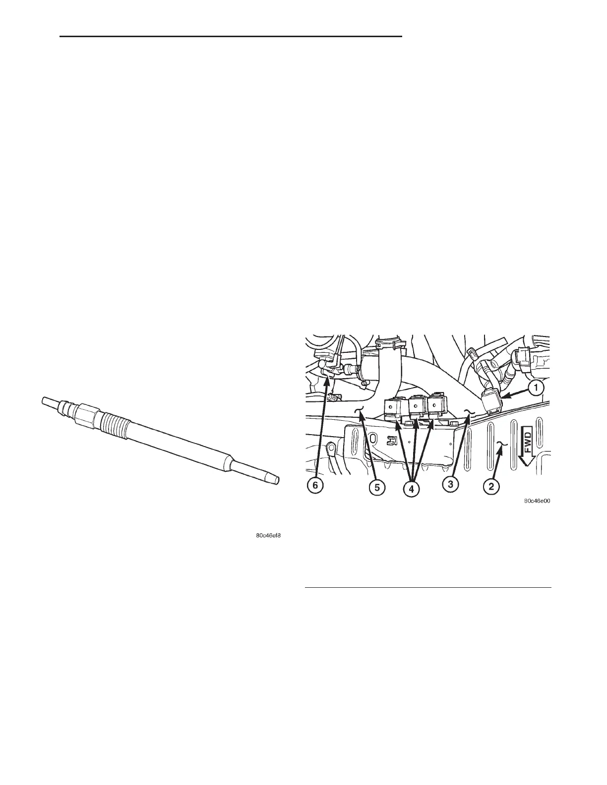
Fig. 1 GLOW PLUG
Fig. 2 RELAY LOCATIONS
1 - GLOW PLUG RELAY
2 - RADIATOR SUPPORT
3 - CHARGE AIR COOLER OUTLET HOSE
4 - COOLING FAN RELAY
5 - UPPER RADIATOR HOSE
6 - EGR SOLENOID
RG IGNITION CONTROL 8Ia-1