INSPECTION - LOWER CONTROL ARM
Inspect lower control arm for signs of damage from
contact with the ground or road debris. If lower con-
trol arm shows any sign of damage, inspect lower
control arm for distortion. Do not attempt to repair
or straighten a broken or bent lower control arm. If
damaged, the lower control arm casting is serviced
only as a complete component.
Inspect both lower control arm isolator bushings
for severe deterioration, and replace as required.
Inspect the rear hydro-bushing for seepage. Both
type rear bushings are serviceable. If the front bush-
ing fails, the lower control arm must be replaced.
Inspect and test the ball joint per the procedure
listed in Lower Ball Joint. (Refer to 2 - SUSPEN-
SION/FRONT/LOWER BALL JOINT - DIAGNOSIS
AND TESTING)
ASSEMBLY
ASSEMBLY - LOWER CONTROL ARM (REAR
BUSHING - STANDARD)
CAUTION: Do not apply grease or any other type of
lubricant other than the silicone lubricant specified
below to the control arm bushing.
(1) Apply Mopar Silicone Spray Lube or an equiv-
alent, to the hole in lower control arm rear bushing.
This will aid in the installation of the bushing on the
lower control arm.
(2) With the lower control arm held securely in a
vise, install bushing on lower control arm. Install
bushing by pushing and rocking the bushing until it
is fully installed on lower control arm. Be sure that
when bushing is installed it is past the upset on the
end of the lower control arm (Fig. 25).
(3) The rear bushing of the lower control arm,
when correctly installed, is to be positioned on the
lower control arm as shown (Fig. 25).
(4) Install lower control arm on vehicle. (Refer to 2
- SUSPENSION/FRONT/LOWER CONTROL ARM -
INSTALLATION)
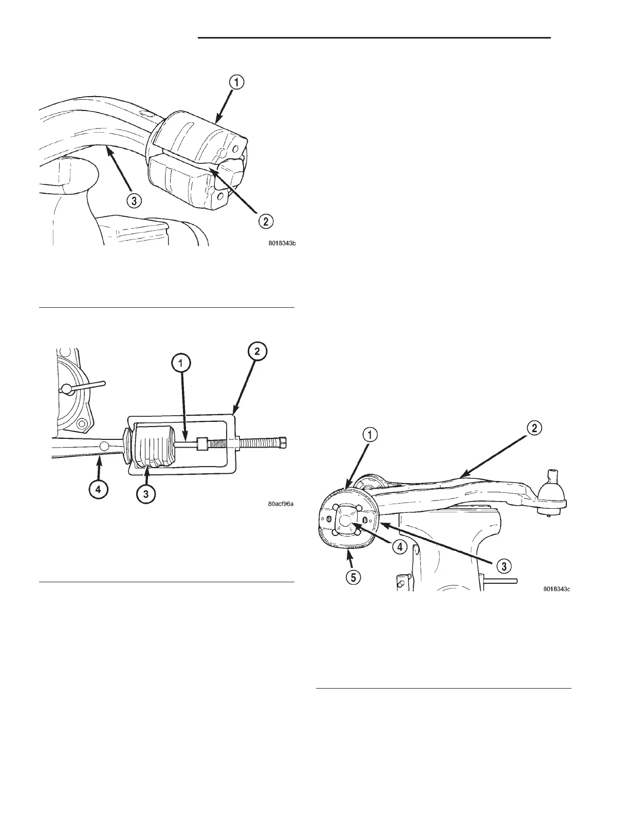
Fig. 23 Slit Lower Control Arm Rear Bushing
1 - REAR BUSHING
2 - SLIT CUT IN BUSHING
3 - LOWER CONTROL ARM
Fig. 24 HYDRO-BUSHING REMOVAL
1 - REMOVAL PIN (8460-3)
2 - BRIDGE (8460-1)
3 - HYDRO-BUSHING
4 - LOWER CONTROL ARM
Fig. 25 Correctly Installed Lower Control Arm
Bushing
1 - ROUND SURFACE OF BUSHING
2 - LOWER CONTROL ARM
3 - LOWER CONTROL ARM REAR BUSHING
4 - UPSET
5 - FLAT SURFACE OF BUSHING
2 - 14 FRONT SUSPENSION RS
LOWER CONTROL ARM (Continued)